Automated boring bar

a multi-functional, automatic technology, applied in boring bars, turning machine accessories, manufacturing tools, etc., can solve the problems of planetary gears being prone to “backlash, unable to accurately track the position of cutting tools, and unable to adjust for non-uniformity in the cylinder wall, etc., to reduce the dependence on highly trained machinists, eliminate inaccuracy, and facilitate the operation of computer control systems

Inactive Publication Date: 2005-09-22
WACHS TECHN SERVICES
View PDF35 Cites 19 Cited by
  • Summary
  • Abstract
  • Description
  • Claims
  • Application Information

AI Technical Summary

Benefits of technology

[0010] Adjusting the position of the cutting tool is achieved via a one-to-one ratio between a servomotor output shaft and a cutting tool adjustment shaft. In other words, one rotation of the servomotor output shaft equals one rotation of the cutting tool adjustment shaft. This eliminates inaccuracies associated with backlash and rounding errors from fractional gear ratios....

Problems solved by technology

Unfortunately, prior devices fail to accurately track the position of the cutting tool during machining operations.
As will be known to persons having ordinary skill in the art, planetary gears are prone to “backlash,” also referred to as “gear lash.” These terms refer to the distance through which one part of connected machinery can be moved without moving the connected parts, resulting...

Method used


Image

  • Automated boring bar
  • Automated boring bar
  • Automated boring bar

Examples


Embodiment Construction

[0027] The present invention relates to an improved apparatus and method for machining pipe.

[0028] In one aspect, the multifunction apparatus is an improved device for machining the inside diameter and outside diameter of pipe, as well as shaping the wall of pipe.

[0029] In another aspect, the invention is an improved method for machining pipe. In particular, the method employs a one-to-one communication ratio between the geared components that control the position of the cutting tool. This eliminates rounding errors associated with conventional gearing systems.

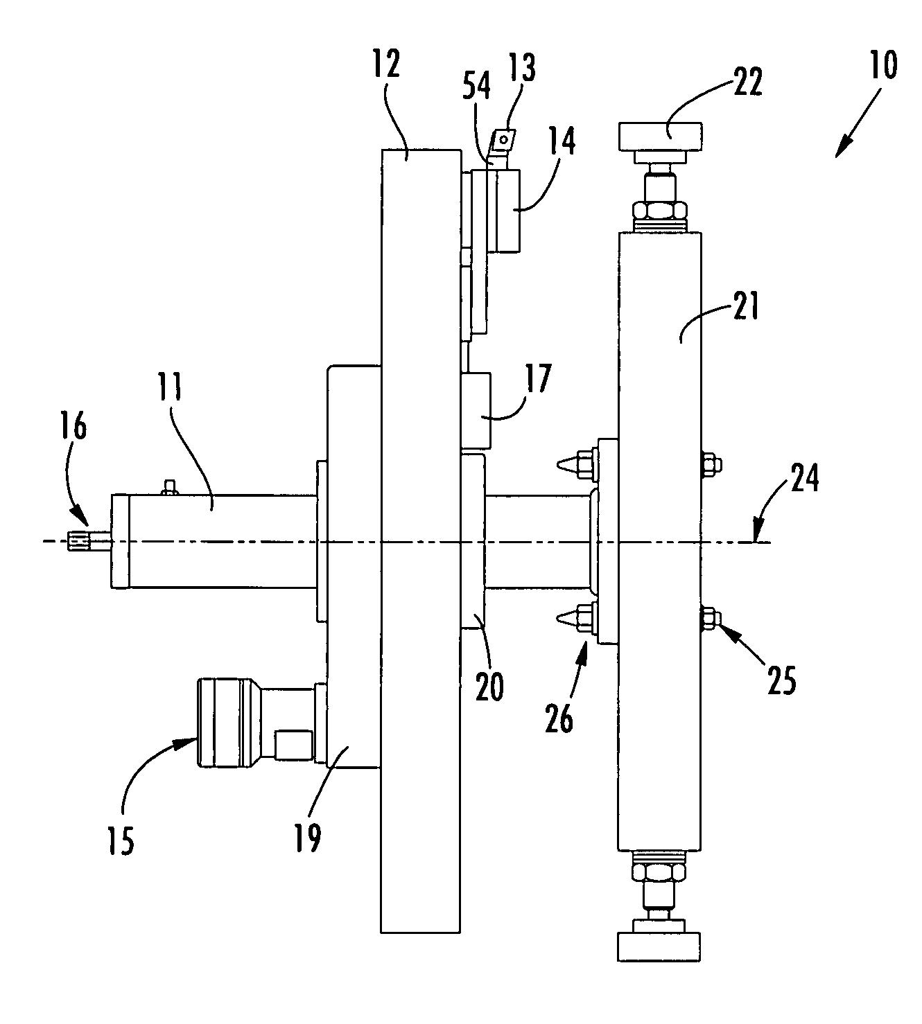
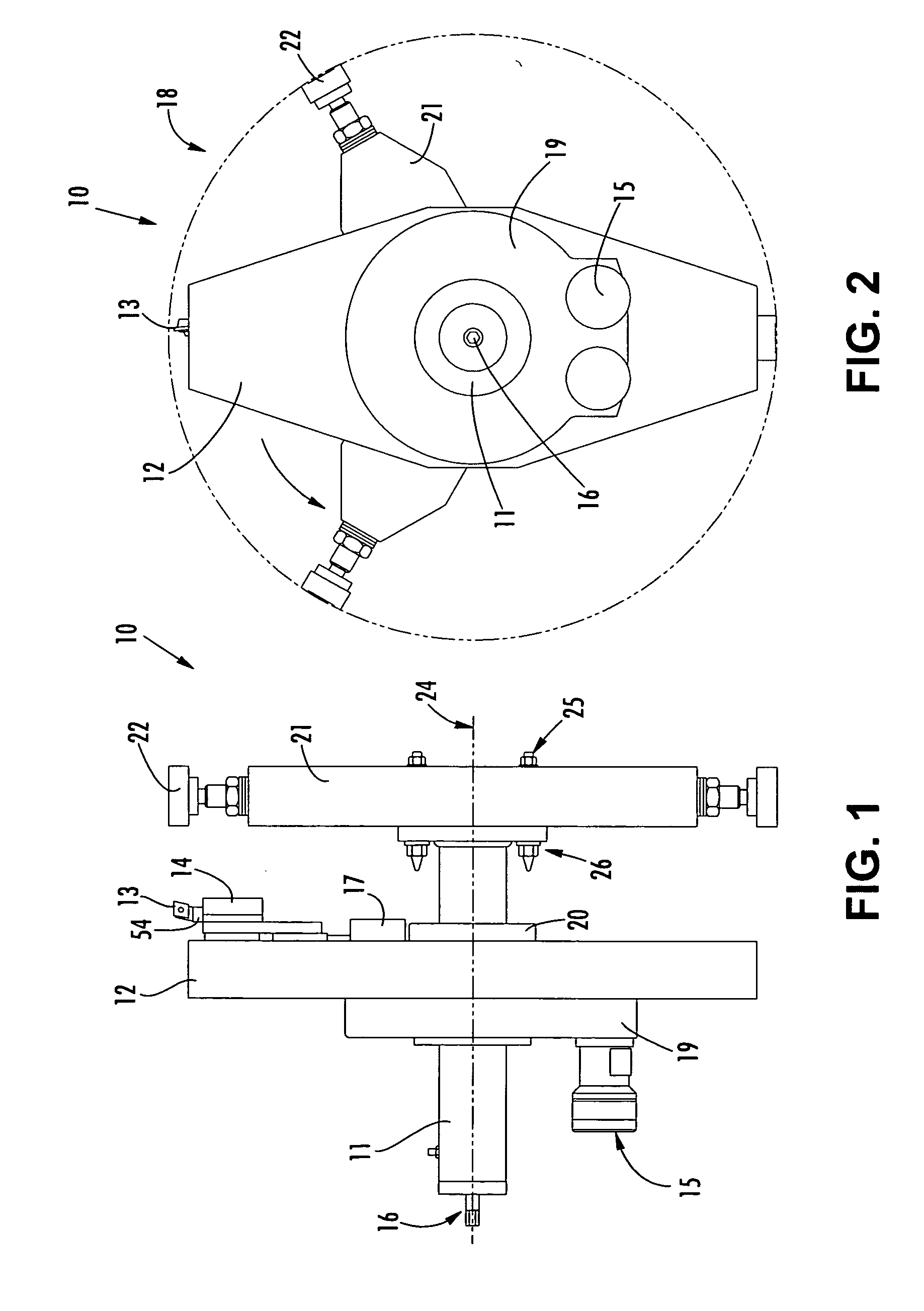
[0030] Referring to FIGS. 1 and 2, a multifunction apparatus 10 for machining cylindrical objects 18 (e.g., pipe) in situ is disclosed.

[0031]FIGS. 1 and 2 illustrate a shaft 11 (e.g., mast) about which a rotary support 12 (or rotary housing) is coupled. The coupling of the rotary support 12 to the mast 11 allows for rotation of the rotary support 12 around the mast 11. Positioned on the rotary support 12 is a tool holder 1...


PUM

PropertyMeasurementUnit
Diameteraaaaaaaaaa

Abstract

The present invention relates to an improved apparatus and method for machining pipe. In one aspect, the multifunction apparatus is an improved device for machining the inside diameter and outside diameter of pipe, as well as shaping the wall of pipe. In another aspect, the invention is an improved method for machining pipe. In particular, the method employs a one-to-one communication ratio between the geared components that control the position of the cutting tool in order to eliminate rounding errors associated with conventional gearing systems.

Description

FIELD OF THE INVENTION [0001] The present invention relates to an automated multifunction tool for machining a metal cylinder. The invention particularly relates to a portable, remotely controlled, multifunction tool that can be positioned inside a pipe to perform precision machining operations. Such operations include, but are not limited to, machining the inside and outside diameters of pipes, as well as facing and transitioning pipe walls. BACKGROUND OF THE INVENTION [0002] Devices for machining pipes or other hollow cylindrical objects are well known. Many such devices include a peripherally mounted, radially adjustable cutting tool. The devices are typically powered by a motor, but may be driven manually as well. The devices are used, for example, to bore, contour, thread, and smooth pipe, valves, and couplings. [0003] One outstanding example is U.S. Pat. No. 4,411,178 to Wachs, which is incorporated entirely herein by reference. Although the Wachs '178 patent discloses a devic...

Claims


Application Information

Patent Timeline
IPC IPC(8): B23B29/034B23B41/00
CPCB23B29/03439Y10T82/12B23B2229/16
Inventor KWECH, HORST W.LARSON, STEVEN R.
Owner WACHS TECHN SERVICES
Why Eureka
Try Eureka