Electric machine with improved cooling system, and method of cooling an electric machine

a technology of electric machines and cooling systems, applied in the direction of dynamo-electric machines, electrical equipment, supports/enclosements/casings, etc., can solve the problems of cooling systems and inability to provide sufficient unheated coolant to winding heads, and achieve the effect of maximum cooling

Inactive Publication Date: 2005-09-22
SIEMENS AG
View PDF31 Cites 29 Cited by
  • Summary
  • Abstract
  • Description
  • Claims
  • Application Information

AI Technical Summary

Benefits of technology

[0011] According to another feature of the present invention, the cooling channels may be formed by axial grooves in the housing or in the stator body. In this way, the provision of axial cooling channels can easily be realized.
[0012] According to another feature of the present invention, a ring-shaped disk may be disposed between each one of the winding heads and the housing for forcing coolant to flow through the winding heads. As a consequence, coolant not only flows around the outside of the winding heads but also provides an effective cooling of the interior of the winding heads.
[0013] According to another feature of the present invention, the housing has end surfaces which may be formed with further coolant ports radially inwardly of the winding heads. The provision of these further coolant ports enables a dir

Problems solved by technology

These types of cooling systems are, however, unable to provide sufficient supply of unheated coolant to t

Method used


Image

  • Electric machine with improved cooling system, and method of cooling an electric machine
  • Electric machine with improved cooling system, and method of cooling an electric machine
  • Electric machine with improved cooling system, and method of cooling an electric machine

Examples


first embodiment

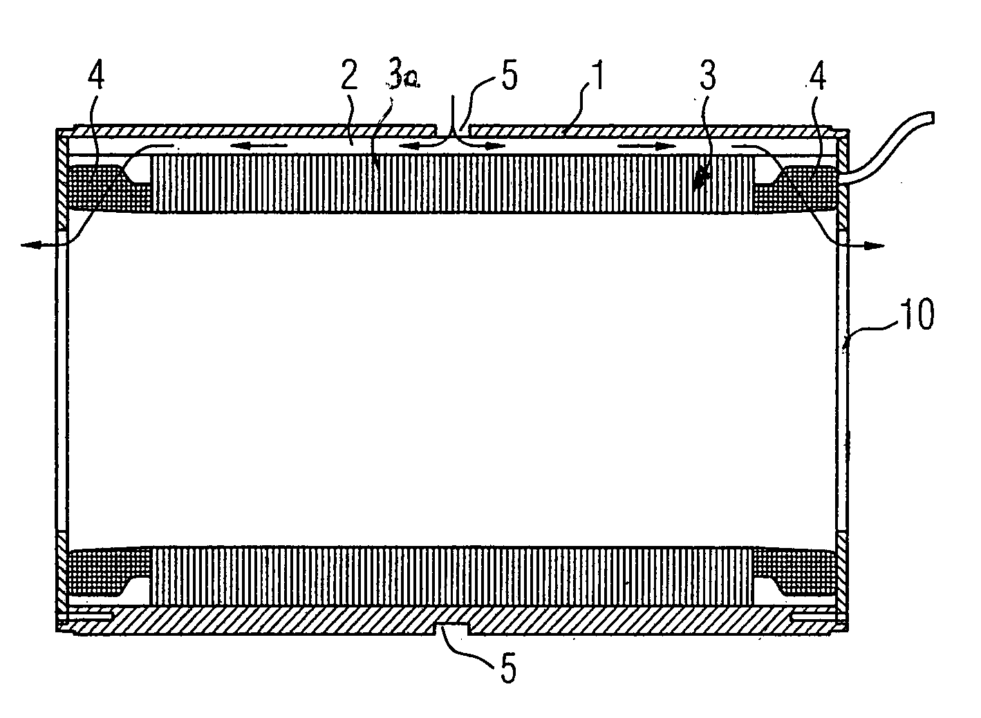
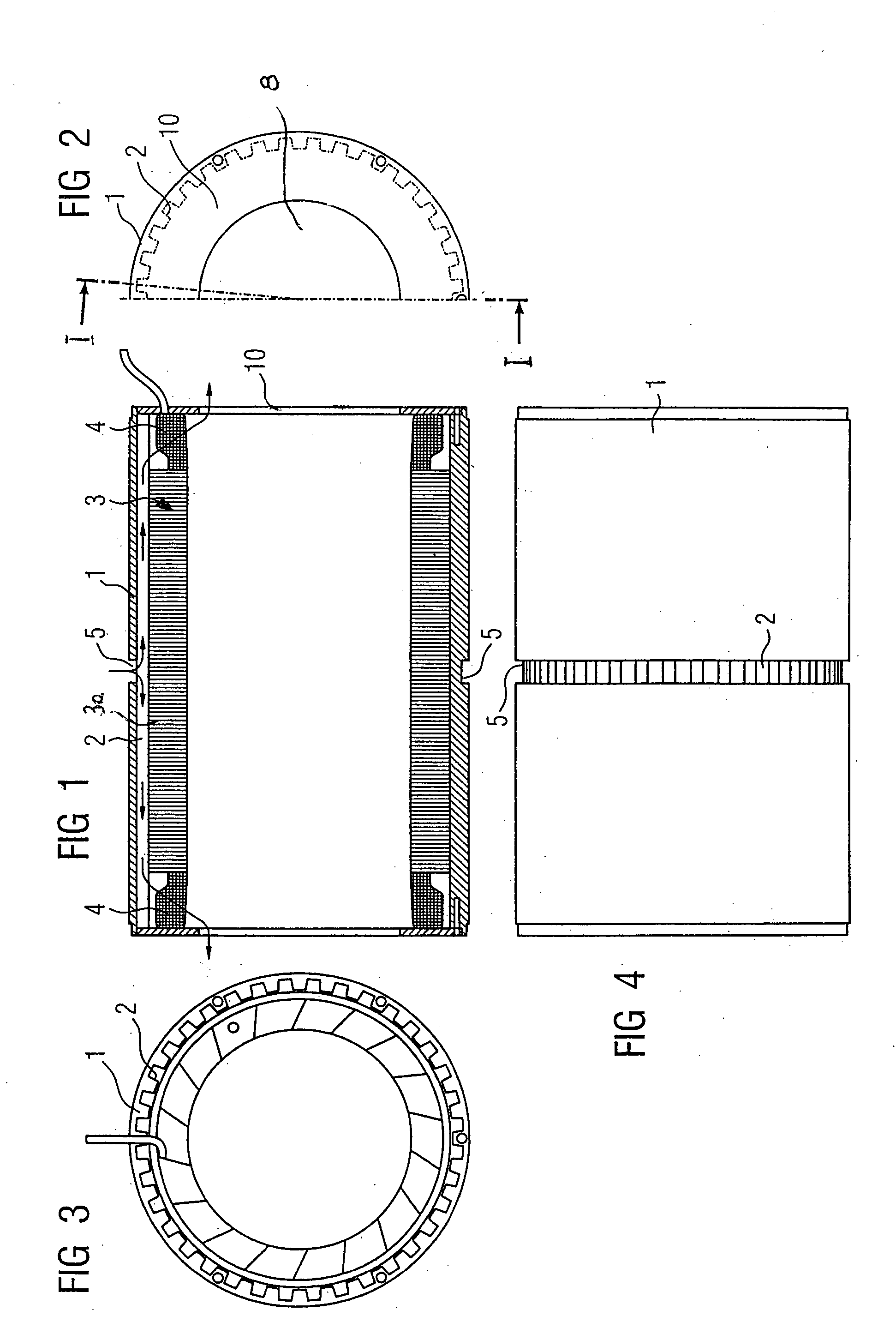
[0027] Turning now to the drawing, and in particular to FIG. 1, there is shown a cross section of an electric machine according to the present invention, taken along the line I-I in FIG. 2. The electric machine includes a housing 1, which is formed with axial grooves 2, and a stator 3, which has a stator body 3a in the form of a stack of laminations and is surrounded by the housing 1. The axial grooves 2 are demarcated by the stator 3 radially to the inside so as to form cooling channels.

[0028] The stator 3 further includes winding heads 4, which are located on both axial ends of the stator body 3a, and ring-shaped end covers 10, which close off the stator 3 and are secured to opposite ends of the housing 1. Provided radially inwards of the winding heads 4, the end covers 10 have each a central port 8 (FIG. 2) for coolant, e.g. gas, air, etc. The covers 10 may either rest against the winding heads 4 or be slightly distanced thereform to define a small gap. Formed in midsection (axia...

second embodiment

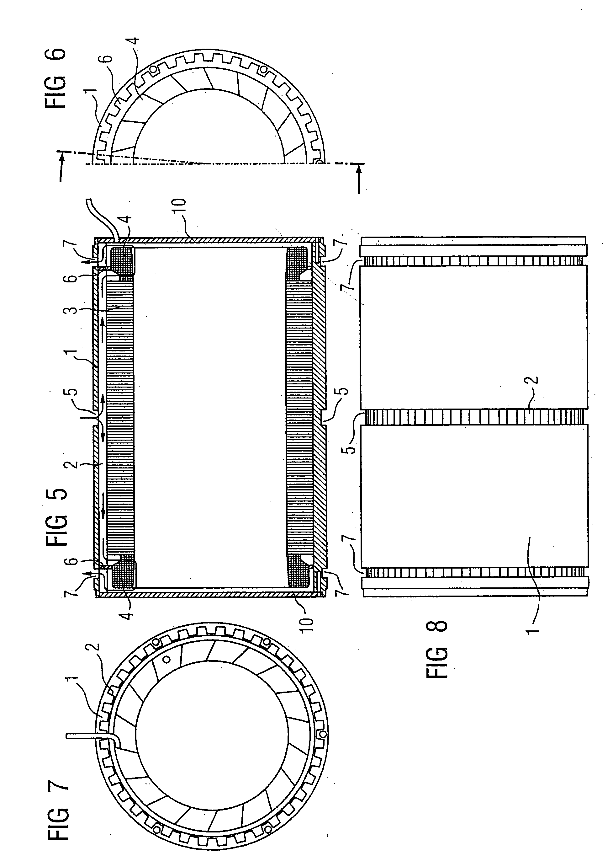
[0033] Turning now to FIG. 5, there is shown a cross section of an electric machine according to the present invention. Parts corresponding with those in FIG. 1 are denoted by identical reference numerals and not explained again. The description below will center on the differences between the embodiments. In this embodiment, provision is made for a ring-shaped disk 6 between each of the winding heads 4 and the housing 1. The disks 6 are contoured to complement a contour of the housing 1 with its grooves 2 so that the disks 6 can be snug fitted in place, as best seen in FIG. 6, which is a partial side view of the electric machine from the right hand side in FIG. 5, with the cover 10 being removed. FIG. 7 is a front view of the electric machine from the left hand side in FIG. 5, with removed disk 6 to illustrate again the cooling channels (grooves) 2 in the housing 1.

[0034] As is further shown in FIG. 5, the end covers 10 are solid and thus devoid of any coolant port. The covers 10 a...

third embodiment

[0037] Referring now to FIG. 9, there is shown a top perspective view of an electric machine according to the present invention, having a housing 1 which is formed in midsection (axial center) with a plurality of pairs of apertures 20, which are evenly spaced apart about the circumference of the housing 1, for introduction of coolant, as indicated by arrows 21. After entry into the housing 1, the coolant, e.g. gas or air, flows in axial direction through cooling channels (grooves) 2 in a direction of arrows 22, and ultimately exits, as indicated by arrows 24, in radial direction through coolant ports 23 formed in proximity of the axial housing end portions. In the nonlimiting example of FIG. 9, the coolant ports 23 have a rectangular configuration, although other configurations are, of course, conceivable as well.

[0038] As shown in FIG. 9, the grooves 2 inside the housing 1 are constructed to end shy of the axial end portions of the housing 1 so that the coolant flow can be routed i...


PUM


Abstract

An electric machine includes a housing defining an axis and having a coolant port disposed in an axial center of the housing, and a cylindrical stator surrounded by the housing and having a stator body in the form of a plurality of stacked laminations, with the stator having opposite axial ends terminating in winding heads. The housing and/or the stator is constructed to have cooling channels which extend in an axial direction and communicate with the coolant port to allow a flow of coolant from the coolant port via the cooling channels to the winding heads, or in opposite direction from the winding heads via the cooling channels to the cooling port.

Description

CROSS-REFERENCES TO RELATED APPLICATIONS [0001] This application claims the priority of German Patent Application, Serial No. 10 2004 013 133.3, filed Mar. 17, 2004, pursuant to 35 U.S.C. 119(a)-(d). BACKGROUND OF THE INVENTION [0002] The present invention relates, in general, to an electric machine with improved cooling system, and method of cooling an electric machine. [0003] Nothing in the following discussion of the state of the art is to be construed as an admission of prior art. [0004] Electric machines of high output power density require the provision of a special system to remove heat and thus are generally equipped with a cooling system by which air or other type of coolant is forced to circulate. German Pat. No. DE 43 11 431 C2 describes a cooling system with radial air channels which are realized by providing a stepped configuration of the active motor part in the form of sheets of different outer diameter or by forming radial grooves in the cooling housing which represe...

Claims


Application Information

Patent Timeline
IPC IPC(8): H02K5/20H02K9/00H02K9/02H02K9/04
CPCH02K9/02H02K5/20H02K5/207
Inventor GEORG, KLAUSGREUBEL, KLAUSMARTIN, JURGEN
Owner SIEMENS AG
Why Eureka
Try Eureka