Magnetic rotation transmitting device, hermetic stirring unit, and electric furnace

a technology of magnetic transmission and transmitting device, which is applied in the direction of dynamo-electric brake/clutch, record information storage, and maintenance of heating chambers, etc., can solve the problems of limiting the size of the magnet, and difficulty in manufacturing a large-sized permanent magnet having an uniform magnetic performan

Inactive Publication Date: 2005-09-22
MAGUNEO
View PDF8 Cites 54 Cited by
  • Summary
  • Abstract
  • Description
  • Claims
  • Application Information

AI Technical Summary

Problems solved by technology

In order to increase the transmitting torque in the conventional-type magnet rotation transmitting device described above, the size of respective magnets in the drive side and the driven side is required to be large, however, it is difficult to manufacture a large-sized permanent magnet having an uniform magnetic performance, and there exists a limit to allow the magnet to be large.

Method used


Image

  • Magnetic rotation transmitting device, hermetic stirring unit, and electric furnace
  • Magnetic rotation transmitting device, hermetic stirring unit, and electric furnace
  • Magnetic rotation transmitting device, hermetic stirring unit, and electric furnace

Examples


first embodiment

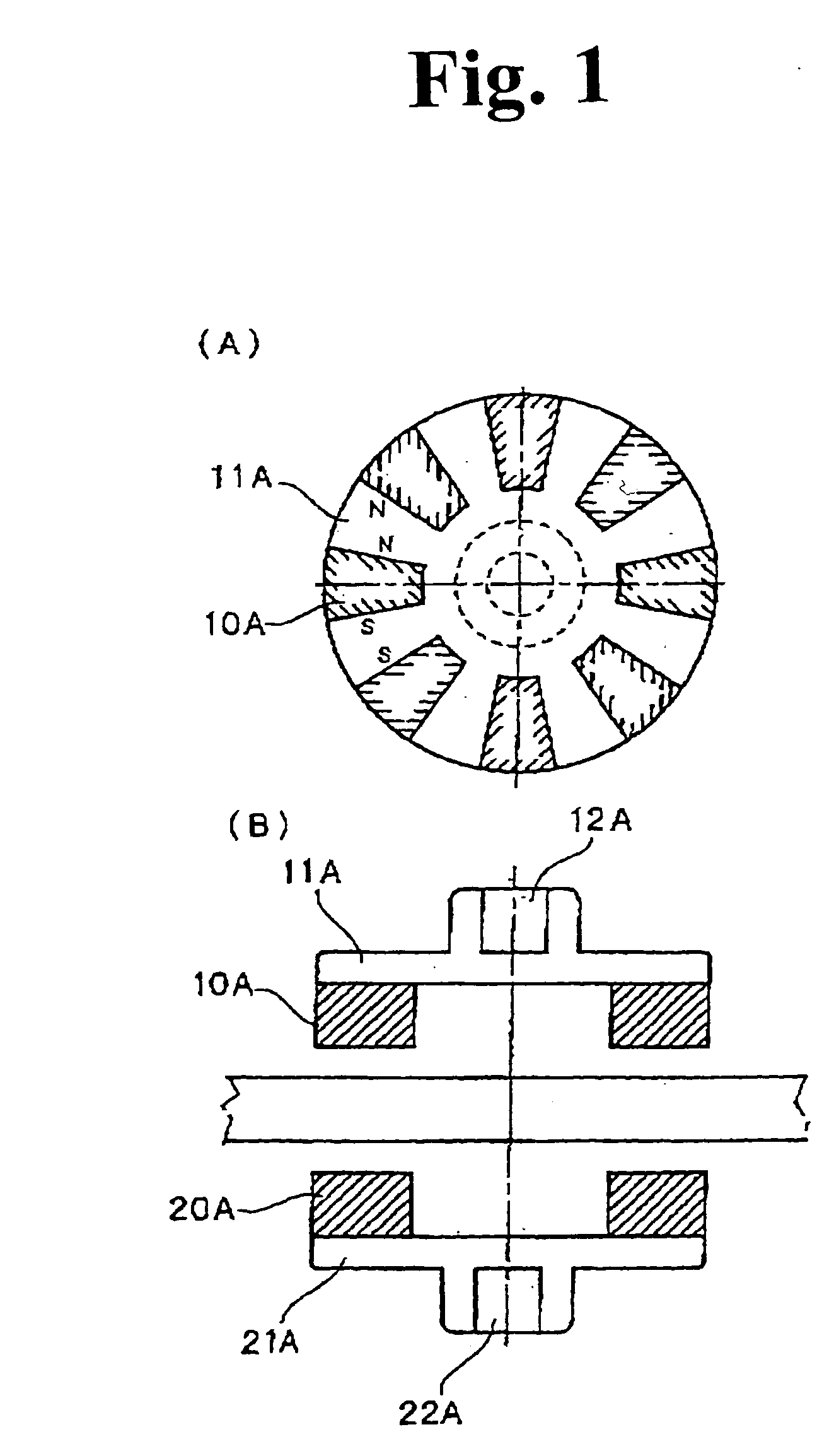
[0065] Hereinafter, a first embodiment of the present invention will be explained with reference to the drawings. FIG. 1A and FIG. 1B are views showing a structure of a magnetic rotation transmitting device as being the first embodiment of the present invention. In FIG. 1, FIG. 1B is a sectional view seen from a side surface of the magnetic rotation transmitting device of the first embodiment of the present invention. FIG. 1A is a bottom view of a first disk 11A (later described) looked up from below in FIG. 1B.

[0066] As shown in FIG. 1A and FIG. 1B, the magnetic rotation transmitting device of the first embodiment of the present invention is constituted by including driving rotation body having a first disk 11A and a first magnet 10A, and a driven rotation body having a second disk 21A and a second magnet 20A.

[0067] The first disk11A is a member made of materials which are not magnetized or which do not tend to be magnetized (nonmagnetic materials), for example, nonmagnetic metal...

second embodiment

[0096] The magnetic rotation transmitting device according to the present invention can be realized by a different structure from the aforementioned first embodiment. Hereinafter, a second embodiment of the present invention will be explained with reference to the drawings. FIG. 4A and FIG. 4B are views showing a structure of the magnetic rotation transmitting device as the second embodiment of the present invention.

[0097] As shown in FIG. 4, the magnetic rotation transmitting device as the second embodiment of the present invention is constituted by including a driving rotation body having a cylinder 11B and first magnets 10B, and a driven rotation body having a column 21B and second magnets 20B.

[0098] The cylinder 11B is the member made of nonmagnetic materials similar to the case of the first embodiment, which is formed to be the cylindrical shape.

[0099] The first magnet 10B is a permanent magnet made of materials similar to the first embodiment, which is formed to be a column...

third embodiment

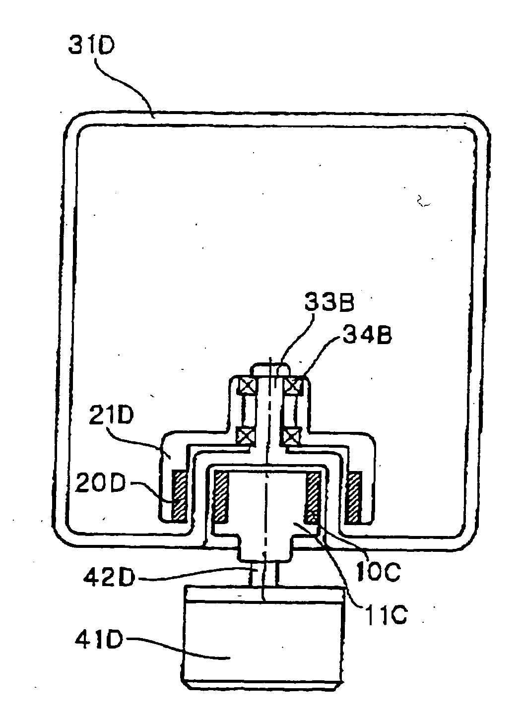
[0115] Hereinafter, a third embodiment of the present invention will be explained with reference to the drawing. FIG. 5 is a view showing a structure of a hermetic stirring unit as being the third embodiment of the present invention. As shown in FIG. 5, the a hermetic stirring unit of the third embodiment of the present invention is constituted by including an axial-type magnetic rotation transmitting device, an electric motor 41A, a hermetic container 31A, a stirring blade 32A, and a driven shaft 52A.

[0116] Since the axial-type magnetic rotation transmitting device is the device having the same structure and operation as the magnetic rotation transmitting device of the first embodiment shown in FIG. 1, the explanation thereof is omitted. The hermetic container 31A, especially in the vicinity of the magnetic rotation transmitting device, is made of materials which are not magnetized or which do not tend to be magnetized (nonmagnetic materials), for example, nonmagnetic metal materi...


PUM

PropertyMeasurementUnit
polarityaaaaaaaaaa
torqueaaaaaaaaaa
distanceaaaaaaaaaa

Abstract

In order to provide a magnetic rotation transmitting device capable of obtaining a large transmitting torque without using a large-sized permanent magnet, in an axial-type magnetic rotation transmitting device, which includes a driving rotation body having one or plural magnetic line(s) in which plural first magnets (10A) are disposed in a circumferential direction on a first disk (11A) at almost equal intervals, a drive source rotationally driving a drive shaft of the driving rotation body, and a driven rotation body having one or plural magnet line(s) in which second magnets (20A) of the same number as the first magnets (10A) are disposed in the circumferential direction on a second disk (21A) at almost equal intervals, symmetrically disposed to, and magnetically coupled with the driving rotation body with a magnetic coupling gap and, which utilizes a magnetic operation and which allows the driven rotation body to rotate by rotationally driving the drive shaft by means of the drive source, the first magnet (10A) has a N-magnetic pole portion and a S-magnetic pole portion, and an extended surface of a boundary surface between the N-magnetic pole portion and the S-magnetic pole portion approximately overlaps with a driving center line as being a rotation center line of the driving rotation body, the second magnet (20A) has the N-magnetic pole portion and the S-magnetic pole portion, and the extended surface of the boundary surface between the N-magnetic pole portion and the S-magnetic pole portion approximately overlaps with a driven center line as being the rotation center line of the driven rotation body, adjacent and facing surfaces of the first magnets (10A) adjacent to each other on the first disk (11A) are disposed so that magnetic pole faces having the same polarity make pairs, and adjacent and facing surfaces of the second magnets (20A) adjacent to each other on the second disk (21A) are disposed so that the magnetic pole faces having the same polarity make pairs.

Description

BACKGROUND OF THE INVENTION [0001] 1. Field of the Invention [0002] The present invention relates to a magnetic rotation transmitting device transmitting the rotation by an electric coupling, a hermetic stirring unit driving a stirring blade inside a hermetic container by the magnetic rotation transmitting device, and an electric furnace driving a pulling shaft of a single crystal or a crucible rotating shaft by using the magnetic rotation transmitting device. [0003] 2. Description of the Related Art [0004] As a conventional magnetic rotation transmitting device transmitting a rotational motion from a drive side to a driven side by magnetically coupling permanent magnets in the drive side with permanent magnets in the side to be driven (driven side), the inventor has developed and proposed the one having a structure such that a right-and-left double pole magnet is used to one of the drive side and the driven side, and a both-surfaces double pole magnet is used to the other side (ref...

Claims


Application Information

Patent Timeline
Patent Type & Authority Applications(United States)
IPC IPC(8): B01F23/30C30B15/30F27B14/04F16H49/00F27B14/06F27B14/10F27D27/00H02K49/10
CPCC30B15/30F27B14/04F27B14/061Y10S366/605F27D27/00H02K49/106H02K49/108F27B14/10B01F33/4532B01F33/4535
Inventor AKIYAMA, SHINICHI
Owner MAGUNEO
Why Eureka
Try Eureka