
Process for injection of a gas with the aid of a nozzle

a technology of gas injection and nozzle, which is applied in the direction of manufacturing converters, coatings, furnace types, etc., can solve the problems of premature wear of the injector, adversely affecting the high performance of the furnace, and reducing the penetration for

Inactive Publication Date: 2003-02-04
LAIR LIQUIDE SA POUR LETUDE & LEXPLOITATION DES PROCEDES GEORGES CLAUDE
View PDF3 Cites 37 Cited by
  • Summary
  • Abstract
  • Description
  • Claims
  • Application Information

AI Technical Summary

Problems solved by technology

Furthermore, the oxygen is not injected uniformly into the bath, which adversely affects the high performance of the furnace, the metal bath being homogeneous neither in temperature nor in chemical composition.
However, the closeness of the metal bath causes premature wear of the injector.
To reduce the wear, the person skilled in the art tends to move the end of the lance away from the surface, to the detriment of the penetration of the jet into the liquid metal.
The problem which results from this type of installation is that the jet of oxygen opens out at the exit of the injector nozzle, which reduces the force of penetration of the jet into the bath and increases the risks of splashes.
While in theory it appears obvious to the person skilled in the art that the increase in the temperature around the jet will cause a reduction in the density of the ambient medium and therefore cause an effect of lower resistance of this medium with respect to a cooler medium, which in theory enables the supersonic jet to remain more "coherent", it has been found, however, that in practice the interactions between the flame and the jet, such as, for example, buoyancy effects, in fact have adverse effects on the jet and reduce the force of penetration.
Furthermore, according to the prior art as described in GB-A-623 881, the arrangement of such a nozzle, in particular a supersonic nozzle, on the walls of the furnace was based on empirical rules leading to a very uncertain effectiveness of this device.
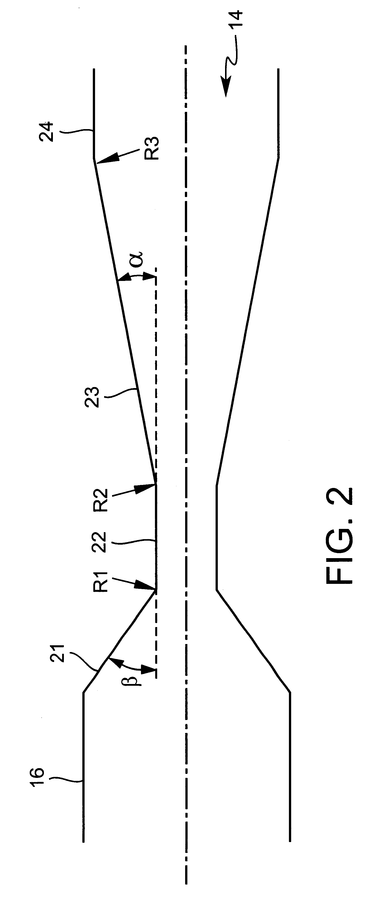
The substantial equalness (difference of less than 10.sup.5 pascals) between these two pressures enables the compression-expansion effects, which result in the generally supersonic jet delivered by this nozzle, to be limited.

Method used


Image

  • Process for injection of a gas with the aid of a nozzle
  • Process for injection of a gas with the aid of a nozzle
  • Process for injection of a gas with the aid of a nozzle

Examples


Embodiment Construction

Numerical example of application in an electric arc furnace:

M=2.2 is chosen, corresponding to a value suitable for injection of oxygen into steel. This velocity can be realized in all steel works at the flow rates usually used. It represents a good compromise between the available pressure and flow rate and the velocity of the jet.

Volume flow rate=5000 Sm.sup.3 / h

Jet Of O.sub.2 (molar mass=0.032 kg / mole)

Ambient T (inside the furnace)=2000 K

For this case, L=1.93 m.

The flow rate taken as an example corresponds to a flow rate commonly employed in a steel works on an electric arc furnace, the tonnage of which is greater than 100 tonnes. It enables a significant amount of oxygen to be injected, taking into account the time of use of the injector in the course of one smelting. The flow rate of the injector is a function of the local conditions of each steel works. It depends on the type of furnace, the tonnage of the charge, its mode of operation and its type of charging.

This calculation ...


PUM

PropertyMeasurementUnit
Angleaaaaaaaaaa
Angleaaaaaaaaaa
Angleaaaaaaaaaa

Abstract

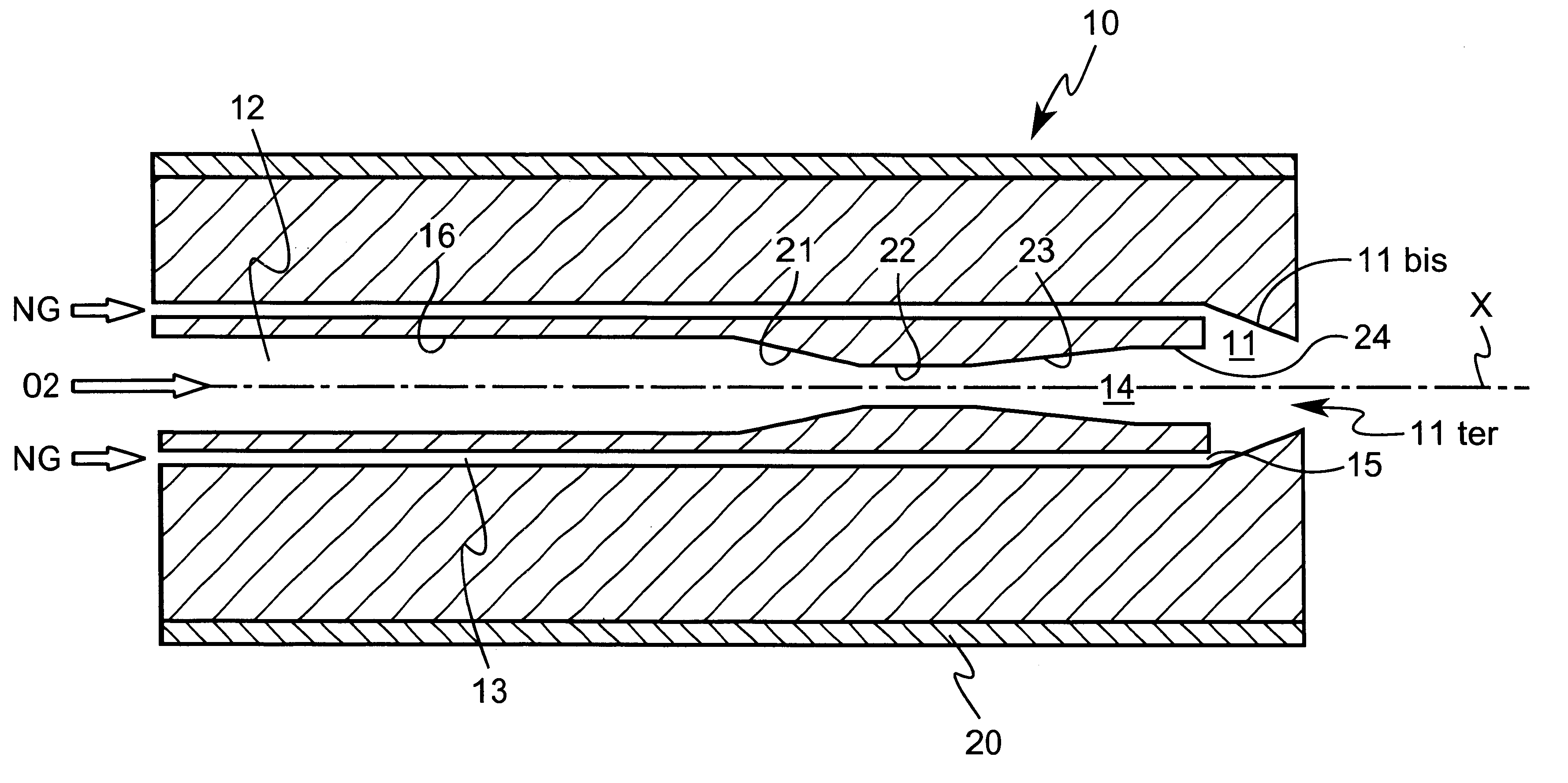
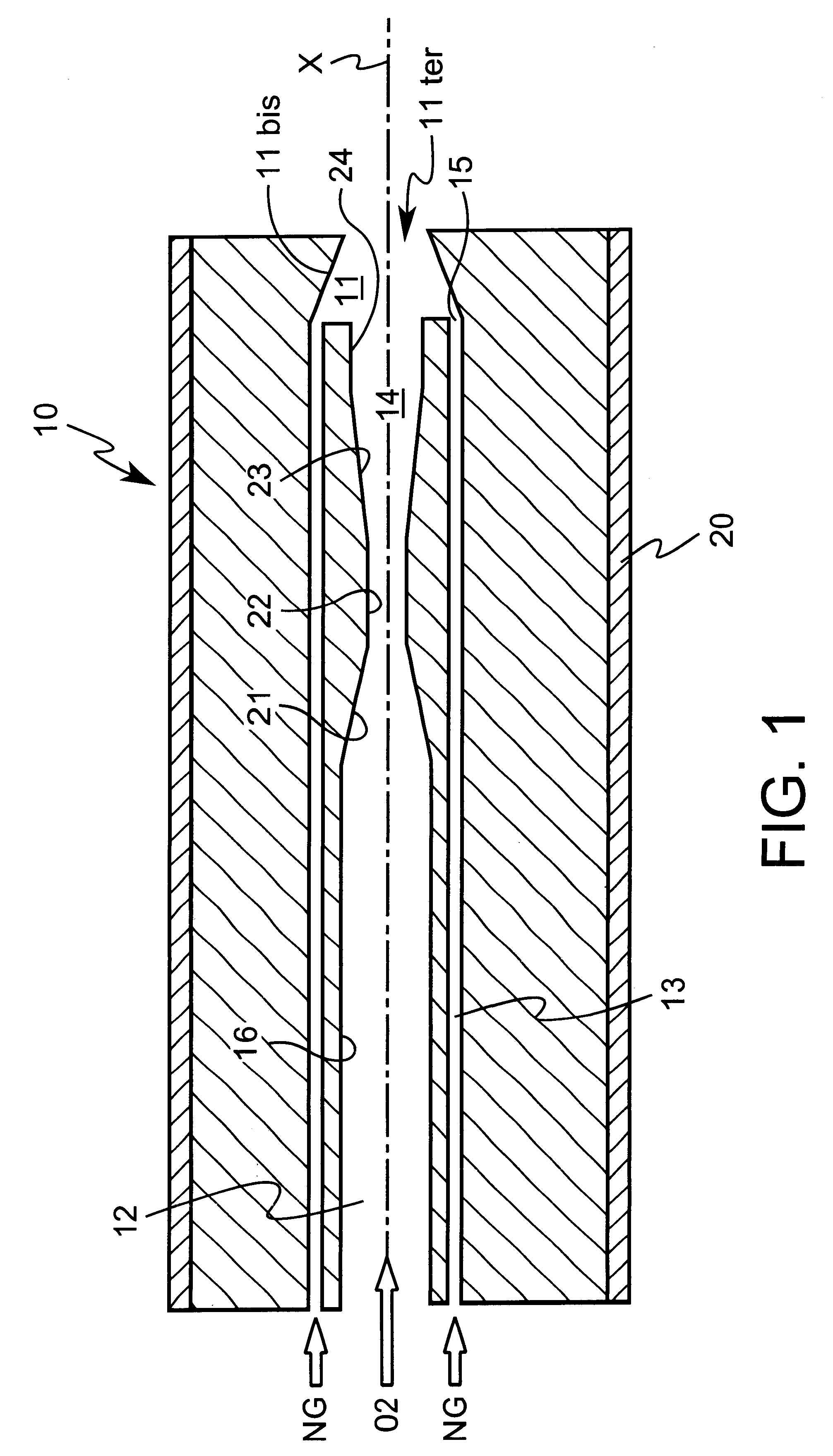
The electric arc furnace is equipped with a supersonic injector comprising a so-called Laval nozzle arranged at a certain distance above the bath. The dimensions of the nozzle are calculated as a function of the desired flow rate of oxygen and the desired velocity of the jet, and the pressure of the oxygen at the intake of the nozzle is such that the static pressure of the jet at the exit of the injector is substantially equal to the pressure of the surrounding atmosphere. Preferably, the injector comprises an annular channel for injection of natural gas, and can be used in burner mode at the start of the melting of scrap iron. The velocity of the oxygen is then subsonic.

Description

PROCESS FOR INJECTION OF A GAS WITH THE AID OF A NOZZLE1. Field of the InventionThe present invention relates to the injection of a gas into a liquid, and in particular a liquid metal. More particularly, it relates to the field of metallurgical reactors, such as melting furnaces, converters of pig iron, of alloyed or non-alloyed steels or of non-ferrous materials, as well as the electric arc furnaces used in particular for the production of steel from scrap iron or scrap iron substitutes, and generally to any injection of a gas into a liquid.2. Description of the Related ArtIn the technology of production of steel in an electric arc furnace, scrap iron or its substitutes are melted by establishing an electric arc between the electrodes of the furnace and the metal such as to supply the energy to melt the metal during the melting phase and to keep it in the molten state during the phase of refining the said metal.During this refining phase, oxygen is used to decarburize the metal and...

Claims


Application Information

Patent Timeline
IPC IPC(8): C21C5/00C21C5/46C21C5/52B05B1/02B05D1/02B05B7/06C21C5/48C21C7/072
CPCC21C5/5217C21C5/4606Y02P10/143Y02P10/20
Inventor ALLEMAND, BRUNOCHAMPINOT, CHRISTELMELEN, STEPHANEVUILLERMOZ, JEAN-CLAUDEFLICHY, SABASTIENLAURENT, JACKY
Owner LAIR LIQUIDE SA POUR LETUDE & LEXPLOITATION DES PROCEDES GEORGES CLAUDE
Learn More