Low-pressure mercury vapor lamp

a mercury vapor lamp and low-pressure technology, which is applied in the direction of low-pressure discharge lamps, gas-filled discharge tubes, cathode-ray/electron beam tube circuit elements, etc., can solve the problems of reduced productivity, operational failure, and inability to secure a sufficient area for bonding the ends of arc tubes

Inactive Publication Date: 2005-09-22
PANASONIC CORP
View PDF19 Cites 11 Cited by
  • Summary
  • Abstract
  • Description
  • Claims
  • Application Information

AI Technical Summary

Benefits of technology

[0028] With this construction, heat emitted from the electrolytic capacitor is allowed to escape to the protrusion, to keep the electrolytic capacitor from being disabled by heat before the arc tube reaches the end of its life.

Problems solved by technology

As a result, the opening occupies a large area of the holder, thereby making it impossible to secure a sufficient area for bonding the ends of the arc tube.
This causes problems such as an operational failure and a productivity decrease.
This, however, causes the diameter of the opening to decrease, which makes it impossible to insert the part of the lighting circuit into the protrusion.

Method used


Image

  • Low-pressure mercury vapor lamp
  • Low-pressure mercury vapor lamp
  • Low-pressure mercury vapor lamp

Examples


Embodiment Construction

[0037] The following describes an embodiment of a low-pressure mercury vapor lamp of the present invention, with reference to the drawings. In the following description, a compact self-ballasted fluorescent lamp is used as an example low-pressure mercury vapor lamp.

1. Construction of a Compact Self-Ballasted Fluorescent Lamp

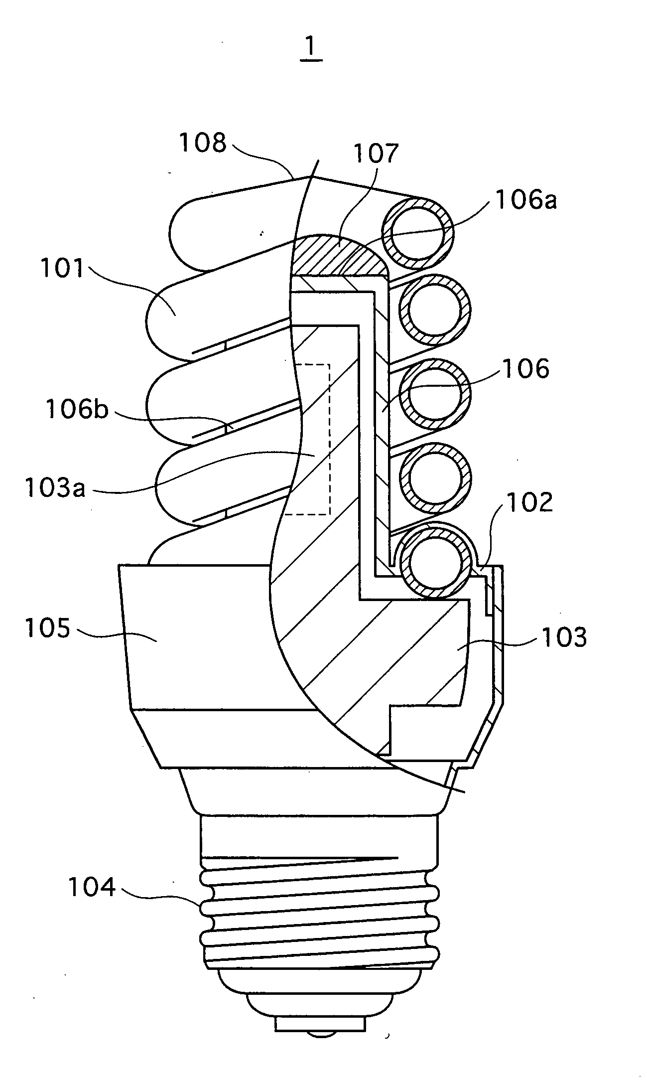
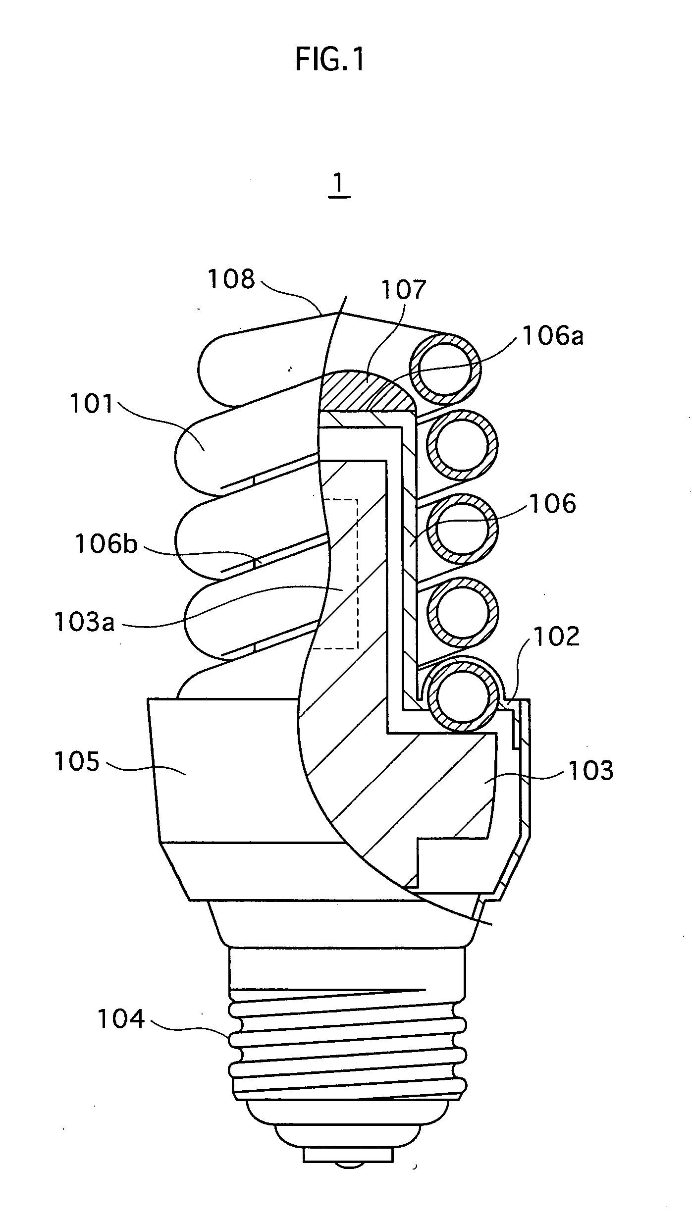
[0038]FIG. 1 is a partial cutaway front view of a compact self-ballasted fluorescent lamp 1 to which the embodiment of the present invention relates. This compact self-ballasted fluorescent lamp 1 corresponds to a 40W incandescent lamp. As shown in the drawing, the compact self-ballasted fluorescent lamp 1 includes an arc tube 101, a holder 102 having a protrusion 106, a lighting circuit 103, a base 104, a case 105, and a bonding unit 107.

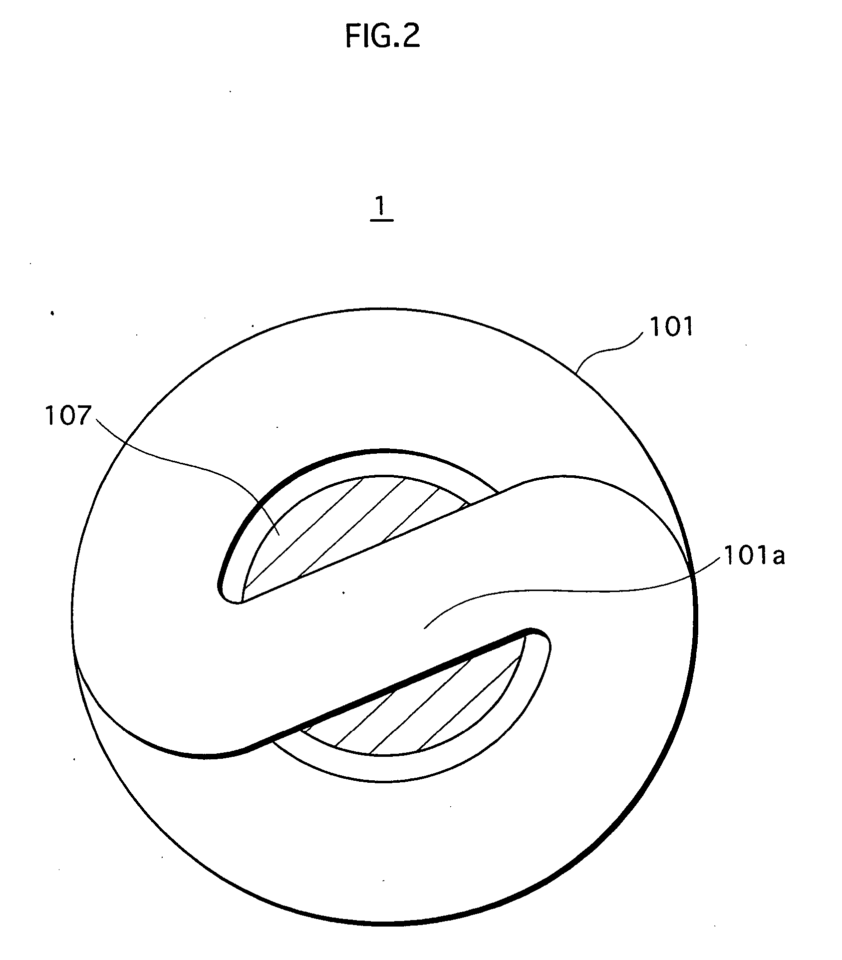
[0039] The arc tube 101 is formed by bending a straight glass tube in a double spiral. Electrodes (not illustrated) are sealed at both ends of the arc tube 101. A phosphor is applied to an inner wall of the arc tube 101. The...


PUM


Abstract

A compact self-ballasted fluorescent lamp includes a double-spiral arc tube and a holder. The holder has a tubular protrusion which is surrounded by the arc tube, at a center of its main surface. A closed end of the protrusion and a part of the arc tube facing the end of the protrusion are bonded together using a silicone adhesive. A part of a vertical printed circuit board that is used as a lighting circuit is housed within the protrusion.

Description

[0001] This application is based on applications Nos. 2004-074287 and 2005-058495 filed in Japan, the contents of which are hereby incorporated by reference. BACKGROUND OF THE INVENTION [0002] 1. Field of the Invention [0003] The present invention relates to techniques of reducing in size of a low-pressure mercury vapor lamp such as a compact self-ballasted fluorescent lamp having an arc tube which forms a curved discharge path, without causing an operational failure and a productivity decrease. [0004] 2. Related Art [0005] Compact self-ballasted fluorescent lamps that include an arc tube having a curved discharge path are being actively developed in recent years. Examples of an arc tube having a curved discharge path include aU-type arc tube in which a plurality of U-shaped glass bulbs are connected to form one discharge path, and a spiral-type arc tube in which a straight glass bulb is wound in a double spiral. [0006] Such an arc tube is held by a holder so as to be in a standing ...

Claims


Application Information

Patent Timeline
Patent Type & Authority Applications(United States)
IPC IPC(8): F21S6/00F21V3/02F21V17/00F21Y103/37F21V23/02H01J5/48H01J5/50H01J5/58H01J17/16H01J61/00H01J61/02H01J61/30H01J61/32H01J61/56H01J61/70
CPCH01J5/48H01J61/523H01J61/327H01J5/58
Inventor MIKI, MASAHIROKITAGAWA, HIROKI
Owner PANASONIC CORP
Why Eureka
Try Eureka