Dual bus static tie switch

Inactive Publication Date: 2005-09-22
ENERGY SYST TECH
View PDF2 Cites 9 Cited by
  • Summary
  • Abstract
  • Description
  • Claims
  • Application Information

AI Technical Summary

Benefits of technology

[0012] In use, when a user wishes to shut down either one of the sources, the user first verifies that the buses are synchronized. Then, the user manipulates the controller in order to tie the buses together. For example, the user may press the button or otherwise indicate that the controller is to tie the buses together. The controller triggers all of the

Problems solved by technology

For example, communications and computing equipment are typically required during power interruptions, and are therefore usually considered critical.
However, the prior art systems designed to provide the delivery of redundant power are typically overly complicated, dependant upon mechanical switchgear, or both, and therefore present reliability problems.
These, and simi

Method used


Image

  • Dual bus static tie switch
  • Dual bus static tie switch
  • Dual bus static tie switch

Examples


first embodiment

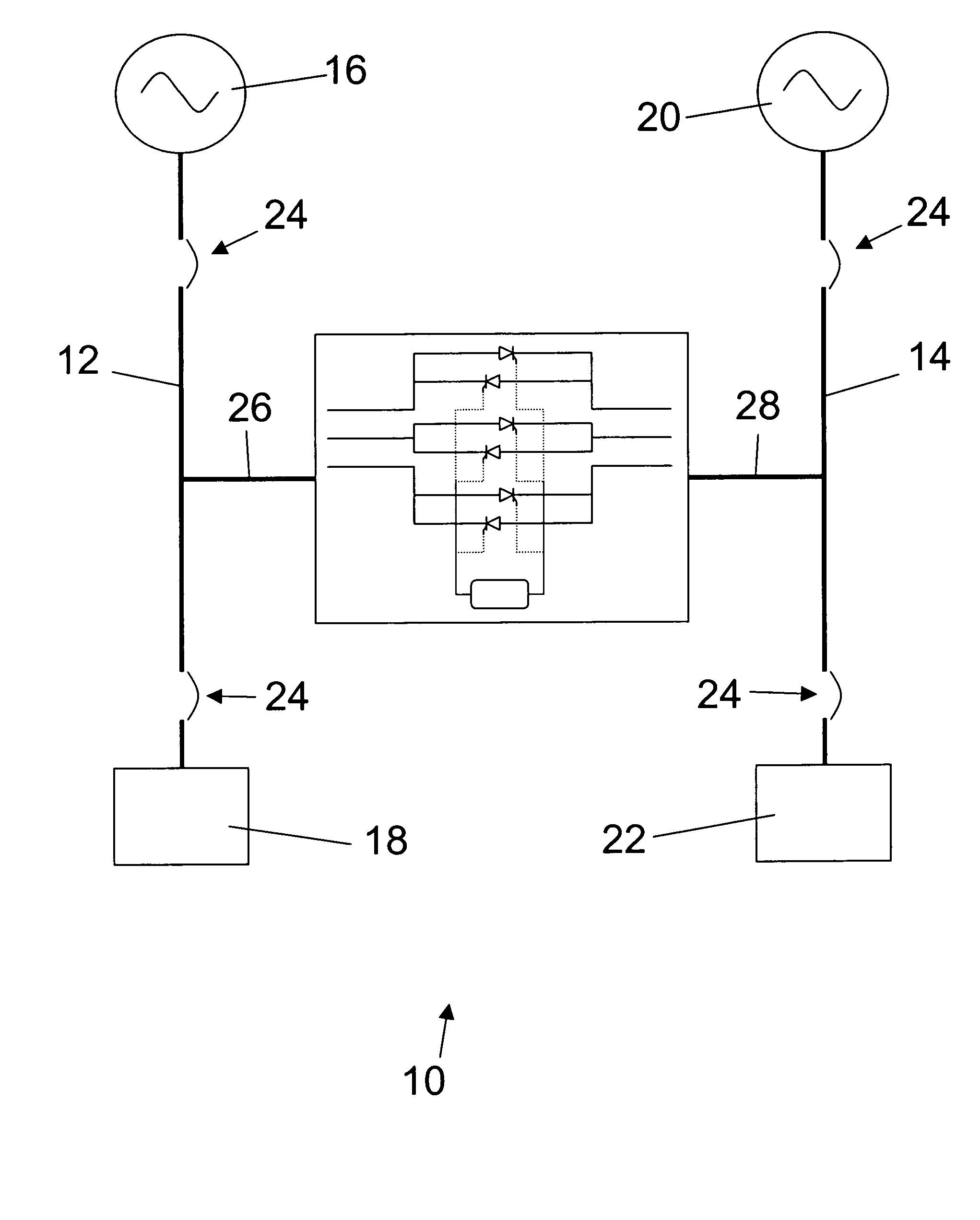
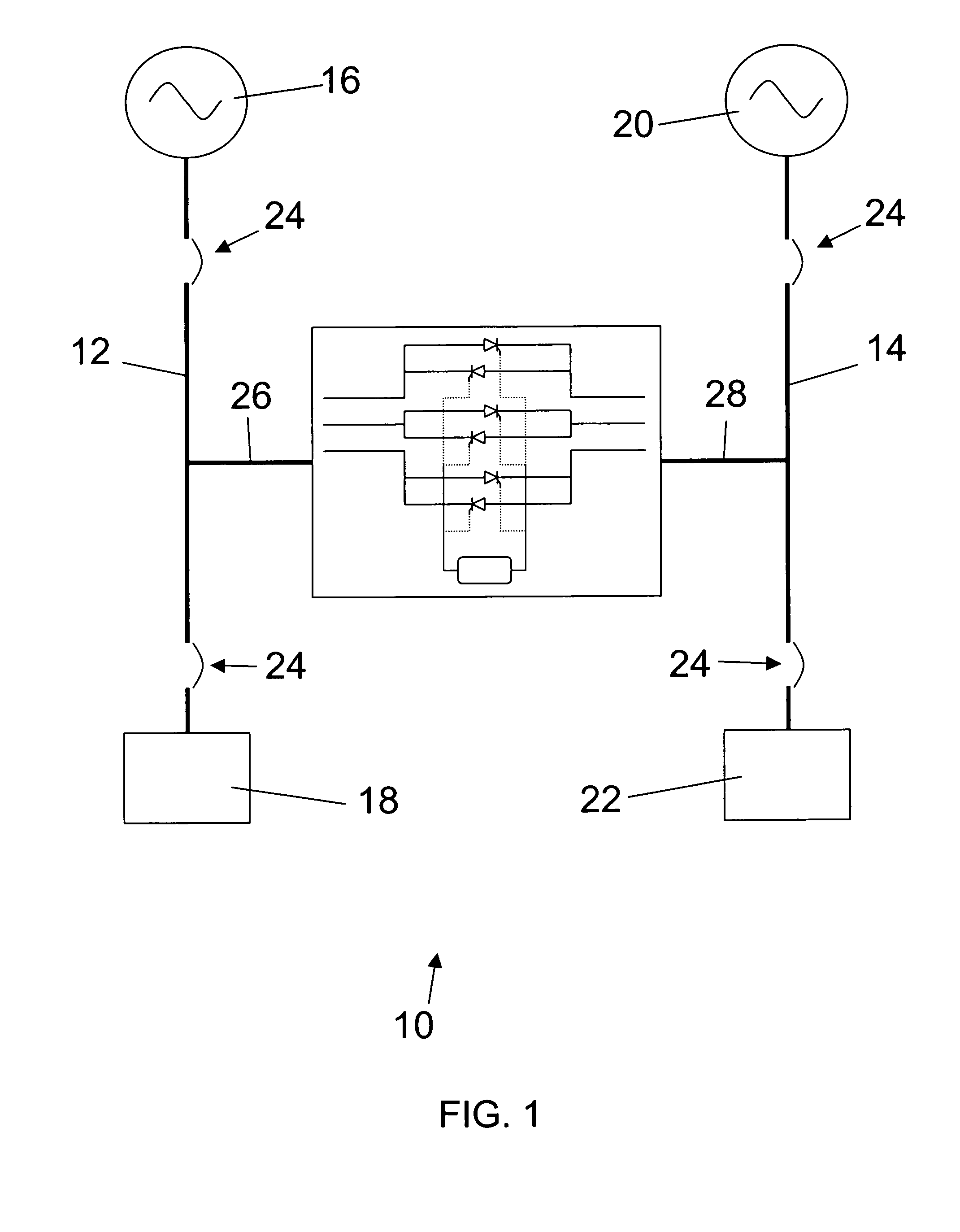
[0022] Referring to FIG. 1, the preferred static tie switch 10 constructed in accordance with a preferred first embodiment of the present invention is illustrated connected between a first and second bus 12,14. The first bus 12 connects a first power source 16 to a first load 18, thereby allowing the first source 16 to directly power the first load 18 under normal operating conditions. Similarly, the second bus 14 connects a second power source 20 to a second load 22, thereby allowing the second source 20 to directly power the second load 22 under normal operating conditions. The buses 12,14 may include circuit breakers 24 operable to isolate any one or more of the sources 16,20 and loads 18,22. During other than normal operations, such as an abnormal event or routine maintenance, one of the sources 16,20 may shut down or need to be shut down. In response to this situation, the switch 10 of the present invention allows both of the loads 18,22 to be powered by either one of the sourc...

second embodiment

[0028] In a preferred second embodiment, as shown in FIG. 3, the switch 10 essentially includes the buses 12,14 and circuit breakers 24 as an integrated package, such that the sources 16,18 and loads 20,22 are connected directly to the switch 10. With all of these components integrated into the switch 10, the switch 10 may include first and second inputs 34,36 and first and second outputs 38,40. In this case, the controller 32 preferably has some control over the circuit breakers 24, such that the controller 32 may open any one or more of the circuit breakers 24 in order to isolate any one or more of the sources 16,20 and / or loads 18,22. Thus, the controller 32 can effectively instantly control power flow from the sources 16,20 and to the loads 18,22. The controller 32 may also include breaker indicators to indicate each circuit breaker's 24 status.

[0029] As shown in FIG. 4, the switch 10 may also include a first and second bypass 42,44 in order to provide for maintenance or replace...


PUM


Abstract

A static tie switch (10) designed to provide the upmost in reliable power to critical equipment, such as communications and computing equipment. The switch uses solid state devices, wherever possible, and preferable uses silicon controlled rectifiers (SCR)s (30) to tie corresponding phases of multiple buses (12,14) together. In the preferred embodiment, the switch (10) broadly comprises three pairs of SCRs (30), one pair for each phase, and a controller (32) to control the SCRs (30). The SCRs (30) can be triggered or biased to selectively allow current to flow between the buses (12,14), thereby allowing a first source (16) to power both a first load (18) and a second load (22). Similarly, the SCRs (30) can be triggered to selectively allow a second source (20) to power both the first load (18) and the second load (22).

Description

BACKGROUND OF THE INVENTION [0001] 1. Field of the Invention [0002] The present invention relates to power systems. More particularly, the present invention relates to a static tie switch that is preferably connected between a first and second bus and operable to selectively tie the buses together. [0003] 2. Description of Prior Art [0004] Many critical devices require redundant sources of power to ensure their continued operation during power interruptions. For example, communications and computing equipment are typically required during power interruptions, and are therefore usually considered critical. However, the prior art systems designed to provide the delivery of redundant power are typically overly complicated, dependant upon mechanical switchgear, or both, and therefore present reliability problems. [0005] For example, one prior art system uses parallel single pole double throw switches to provide power to two loads from selected redundant power sources. These, and similar...

Claims


Application Information

Patent Timeline
IPC IPC(8): H02H7/06H02J9/06
CPCH02J2009/068H02J9/06H02J9/068
Inventor BOSCH, MARTIN S.DARRAH, DAVID J.HUMMER, JAIME J.
Owner ENERGY SYST TECH
Why Eureka
Try Eureka