
Method and apparatus for sensor network routing

a sensor network and routing technology, applied in the field of communication networks, can solve the problems of depleting the performance of the network, affecting the service life of the network, so as to reduce the multiplicity of messages attendants

Inactive Publication Date: 2005-09-22
RPX CLEARINGHOUSE
View PDF5 Cites 168 Cited by
  • Summary
  • Abstract
  • Description
  • Claims
  • Application Information

AI Technical Summary

Benefits of technology

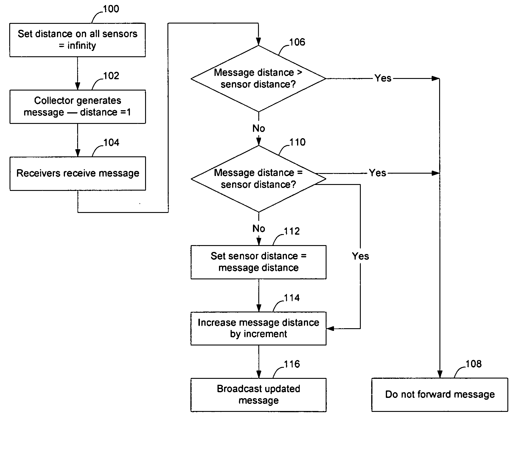
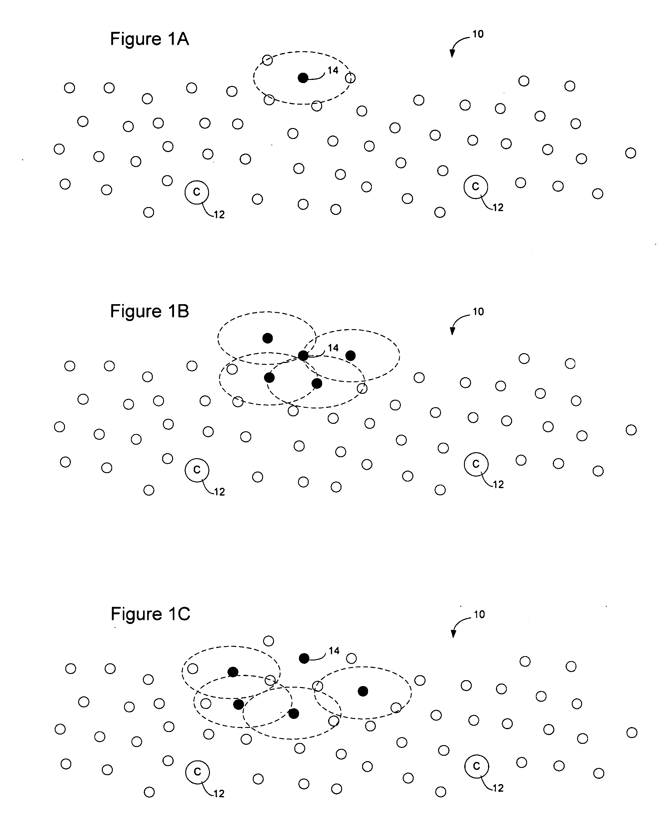
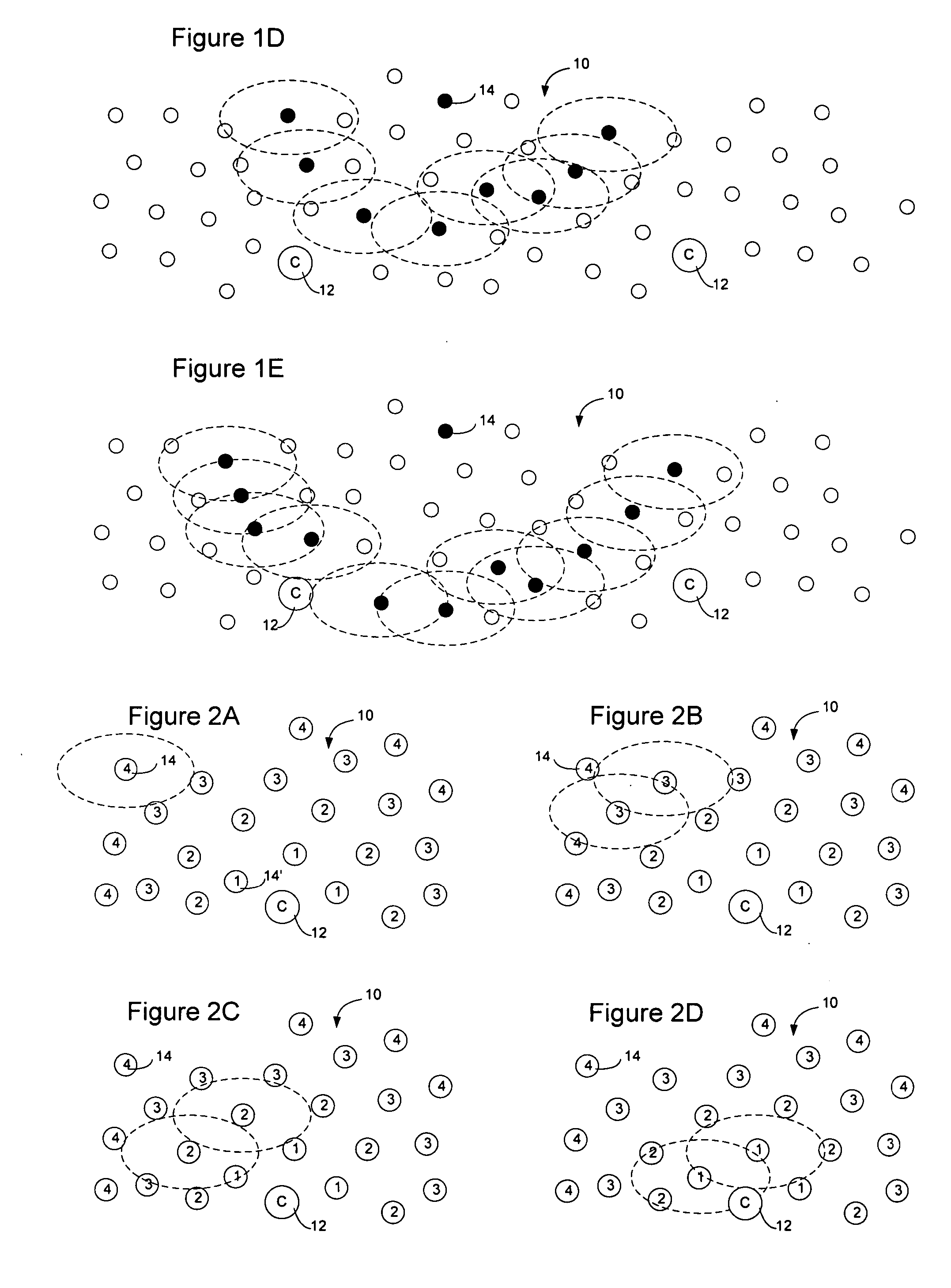
[0009] The present invention overcomes these and other constraints by providing a method and apparatus for sensor network routing. According to an embodiment of the invention, distance calculation messages are used to set distance values on sensors relative to collectors on the network. The distance values enable messages to be routed only toward the collectors to thereby reduce the multiplicity of messages attendant to transmission of a message on the network. Additionally, self-assigned key information may be added to distance calculation messages propagating in a sensor network to enable routes to be determined through the network. By storing the key information associated with the route, the sensors can direct a message to a collector along one or more unique paths and the collector may direct a message back toward the sensor along the same path(s). Optionally, traffic level indications or other network condition information may also be added to the distance calculation messages to allow diverse paths to be selected on the sensor network.

Problems solved by technology

While this presents a viable manner to transmit information reliably through the network, it causes excessive replication of messages which can cause congestion on the network and waste resources of the sensors on the network.
Additionally, several of the traditional network routing techniques require the transmission of routing updates between sensors, which themselves may deplete performance of the network and may not be able to be implemented given the limited resources of the sensors.

Method used


Image

  • Method and apparatus for sensor network routing
  • Method and apparatus for sensor network routing
  • Method and apparatus for sensor network routing

Examples


Embodiment Construction

[0020] The following detailed description sets forth numerous specific details to provide a thorough understanding of the invention. However, those skilled in the art will appreciate that the invention may be practiced without these specific details. In other instances, well-known methods, procedures, components, protocols, algorithms, and circuits have not been described in detail so as not to obscure the invention.

[0021] According to an embodiment of the invention, distance information, as well as self-assigned key information, may be added to distance calculation messages in a sensor network to reduce the message volume on the network and optionally enable routes to be determined through the network. Additionally, traffic level indicators may also be added to allow diverse paths to be selected on the sensor network.

[0022] In the following description, it will be assumed that sensors have a sensor ID or other information associated with them so that they may be identified on the...


PUM


Abstract

Sensor network routing uses distance information of sensors relative to a collector node, optionally along with non-unique key information, to route broadcasts from addressless sensors to a selected addressless collector. Distance calculation messages (DCMs) are used to set distance values on sensors relative to collectors. The distance values enable messages to propagate toward collectors to reduce the number of broadcasts. Self-assigned key information may be added to DCMs propagating in the network to enable routes to be determined through the network without assigning addresses to the participants. By storing the key information associated with the route, and causing sensors to only rebroadcast a message if the message contains a matching key at the matching distance position, broadcast paths may be created on the network. Optionally, diverse collectors and paths may be selected on the network by exchanging traffic condition indications and preferentially selecting paths with better traffic conditions.

Description

BACKGROUND OF THE INVENTION [0001] 1. Field of the Invention [0002] The present invention relates to communication networks and, more particularly, to a method and apparatus for sensor network routing. [0003] 2. Description of the Related Art [0004] Data communication networks may include various computers, servers, nodes, routers, switches, bridges, hubs, proxies, and other network devices coupled to and configured to pass data to one another. These devices will be referred to herein as “network elements.” Data is communicated through the data communication network by passing protocol data units, such as Internet Protocol packets, Ethernet Frames, data cells, segments, or other logical associations of bits / bytes of data, between the network elements by utilizing one or more communication links between the devices. A particular protocol data unit may be handled by multiple network elements and cross multiple communication links as it travels between its source and its destination ov...

Claims


Application Information

Patent Timeline
IPC IPC(8): H04L12/56H04W40/00H04W40/28H04W84/18
CPCH04L45/20H04W84/18H04W40/28H04W40/00
Inventor ASHWOOD-SMITH, PETERFEDYK, DONALD
Owner RPX CLEARINGHOUSE
Learn More