Automatic analyzer

an analyzer and automatic technology, applied in the field of automatic analyzers, can solve the problems of less analysis time, less reagent replacement operations, and reagent containers other than the intended reagent containers, so as to improve the analysis speed of the apparatus, reduce the time interval between reagent-container replacement operations, and increase the consumption of reagents

Active Publication Date: 2005-09-22
HITACHI HIGH-TECH CORP +1
View PDF8 Cites 60 Cited by
  • Summary
  • Abstract
  • Description
  • Claims
  • Application Information

AI Technical Summary

Benefits of technology

[0006] With the enhancement of the analysis speed of the apparatus, the consumption of reagents increases, and time intervals between reagent-container replacing operations have been reduced. In conventional apparatuses, once a reagent container has been set, it can be continuously used for a considerably long time period without being replaced, whereas, in recent years, it is conceivable that a reagent container set in the morning will have to be replaced on the same day. In the automatic analyzer set forth in the above-described Japanese Patent No. 3274325, when attempting to replace a reagent container, it is necessary for an operator to temporarily interrupt the measurement, take out an reagent container from a cold-storage chamber located at another place, and input information such as the kind of reagent, lot number, and the like into the automatic analyzer before setting the reagent container in the automatic analyzer. Therefore, the problem occurs that more the number of replacing operations of reagent, the less the time for analysis. In addition, there is a possibility that, when attempting to taking out a reagent from the cold-storage chamber, a reagent container other than the intended reagent container is taken out and set in error.

Problems solved by technology

Therefore, the problem occurs that more the number of replacing operations of reagent, the less the time for analysis.
In addition, there is a possibility that, when attempting to taking out a reagent from the cold-storage chamber, a reagent container other than the intended reagent container is taken out and set in error.

Method used


Image

  • Automatic analyzer
  • Automatic analyzer
  • Automatic analyzer

Examples


first embodiment

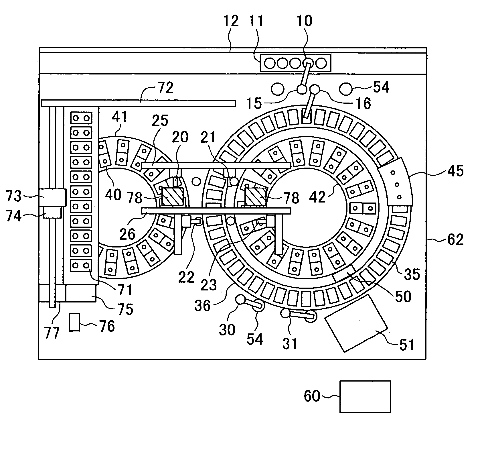
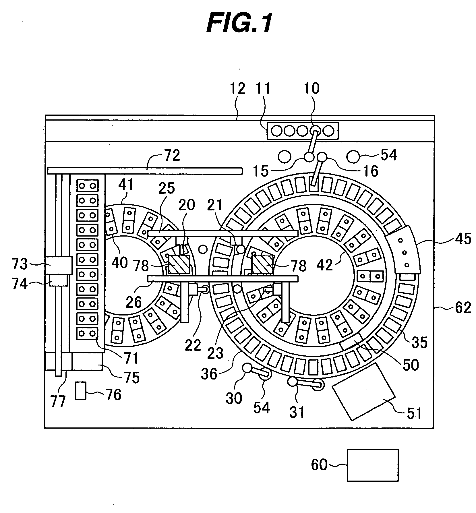
[0025]FIG. 1 is a top view of an automatic analyzer having a supplemental reagent container storage case, according to a first embodiment of the present invention. Referring to FIG. 1, in a cabinet 62, a plurality of reaction vessels 35 is regularly arranged along the circumference of a reaction disk,36 that is rotatable in one direction. A reagent disk 42 is disposed inside the reaction disk 36 while a reagent disk 41 is disposed outside the reaction disk 36. Each of the reagent disks 41 and 42 is arranged rotatably in opposite directions, and is adapted so as to be rotated in a direction such that the rotational angle necessary to convey a required reagent to the respect one of reagent probes 20 and 21 is smaller. Reagent containers 40 can be arranged along the entire circumferences of the reagent disks 41 and 42. The reagent containers 40 contain a plurality of various kinds of reagents respectively, being the first reagent storege means used for the alayzing operation. One reage...

second embodiment

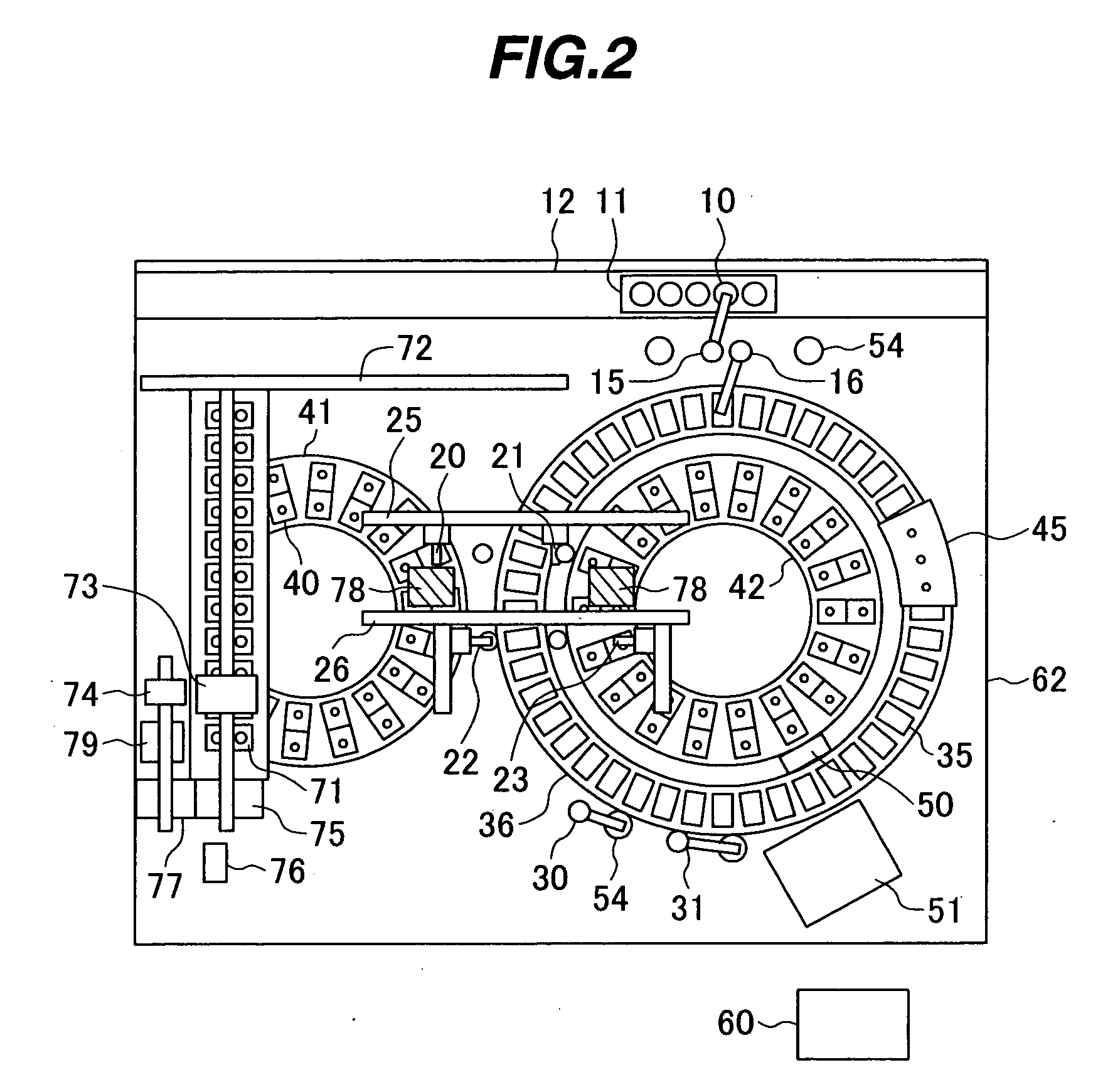
[0037]FIG. 2 is a top view of an automatic analyzer having a supplemental reagent storage case, according to a second embodiment of the present invention. Here, the reagent holding means 73 and reagent container uncapping means 74 above the supplemental reagent storage case 71 are disposed and driven independently of each other. Also, an uncapping position 79 is independently provided. In this embodiment, while performing uncapping operation, the conveyance of a reagent container 40 that is subsequently to be mounted on the reagent disk, or the mounting of a new reagent on the supplemental reagent storage case 71 can be performed, thereby enabling a more efficient supplementation of reagent.

[0038] In this embodiment also, it is possible to lighten the burden of reagent management imposed on the operator, minimize the analysis interruption due to the reagent registration and reagent replacement, load a large number of reagents, and implement a high throughput.

third embodiment

[0039]FIG. 3 is a top view of an automatic analyzer having a supplemental reagent storage case, according to a second embodiment of the present invention. A supplemental reagent storage case 71, serving as the second reagent storage means, is disposed above the reagent disk 41. The supplemental reagent storage case 71 can mount thereon a plurality of reagent containers 40. A rail 72 is provided above the supplemental reagent storage case 71 and the reagent disk 42. To the rail 72, there is provided reagent holding means 73 that is movable along the rail 72 in the three axis directions. Also, a rail 80 is provided above the supplemental reagent storage case 71. To the rail 80, there is provided reagent container uncapping means 74 that is movable along the rail 80 in the three axis directions. A reagent container mounting opening 75 is formed in front of the supplemental reagent storage case 71. In the vicinity of the reagent container mounting opening 75, there is provided a barcode...


PUM

PropertyMeasurementUnit
timeaaaaaaaaaa
pressureaaaaaaaaaa
circumferenceaaaaaaaaaa

Abstract

An automatic analyzer is disclosed that dispenses a sample and a reagent into each of a plurality of reaction vessels to allow them to react with each other, and that measures the liquid formed as a result of the reaction. This automatic analyzer includes a first reagent storage case for storing the reagent to be used for the reaction, a second reagent storage case for storing the reagent for supplemental purpose, and a reagent conveying unit for conveying the reagent from the second reagent storage case to the first reagent storage case.

Description

BACKGROUND OF THE INVENTION [0001] 1. Field of the Invention [0002] The present invention relates to an automatic analyzer that performs a quantitative / qualitative analysis of a biological sample such as blood, urine, or the like, and more particularly, to a novel automatic analyzer capable of analyzing more analysis items. [0003] 2. Description of the Related Art [0004] In the field of automatic analysis, a random access type automatic analyzer, which uses a plurality of reaction lines at random, has been developed, and has dramatically improved the processing capability of analysis. As a consequence, the consumption of reagents has speeded up and opportunities to replace reagents have increased. Also, with the advances in measurement techniques, the demand for measurements of extensive analysis items is growing. Therefore, it is desired to increase the number of reagents mountable in a reagent storage case. [0005] In order to increase the number of mountable reagent containers, fo...

Claims


Application Information

Patent Timeline
Patent Type & Authority Applications(United States)
IPC IPC(8): G01N35/00G01N35/02G01N35/04G01N35/10
CPCG01N35/1002Y10T436/111666Y10T436/11Y10T436/113332Y10T436/114998
Inventor HANAWA, MASAAKIYAMAZAKI, ISAOTOKIEDA, HITOSHINISHIDA, MASAHARUSHIBA, MASAKIEIKMEIER, HEINOKAPPELHOFF, DIETMARMOLLERS, CHRISTOPHSATTLER, STEPHAN
Owner HITACHI HIGH-TECH CORP
Why Eureka
Try Eureka