
Device and method for repair analysis

Active Publication Date: 2012-05-24
SK HYNIX INC
View PDF1 Cites 4 Cited by
  • Summary
  • Abstract
  • Description
  • Claims
  • Application Information

AI Technical Summary

Benefits of technology

[0009]An exemplary embodiment of the present invention is directed to reduce the area of a repair analysis device, which calculates a repair solution by analyzing information about a fault cell, and to increase the analysis speed thereof.

Problems solved by technology

However, as the memory capacity has increased, it has become difficult to fabricate a memory chip without any fault cell.
However, the “intelligent solve first” method of the prior art 2 excessively increases a redundancy analysis operation time if the number of faults (i.e., cells) increases or the distribution thereof becomes complicated.
Also, the “intelligent solve first” method of the prior art 2 cannot secure the optimal repair solution.
However, a register capacity for storing fault addresses is insufficient, thus failing to accurately reproduce a fault phenomenon.
Therefore, the ESP method cannot secure the optimal repair solution and analysis result.

Method used


Image

  • Device and method for repair analysis
  • Device and method for repair analysis
  • Device and method for repair analysis

Examples


Embodiment Construction

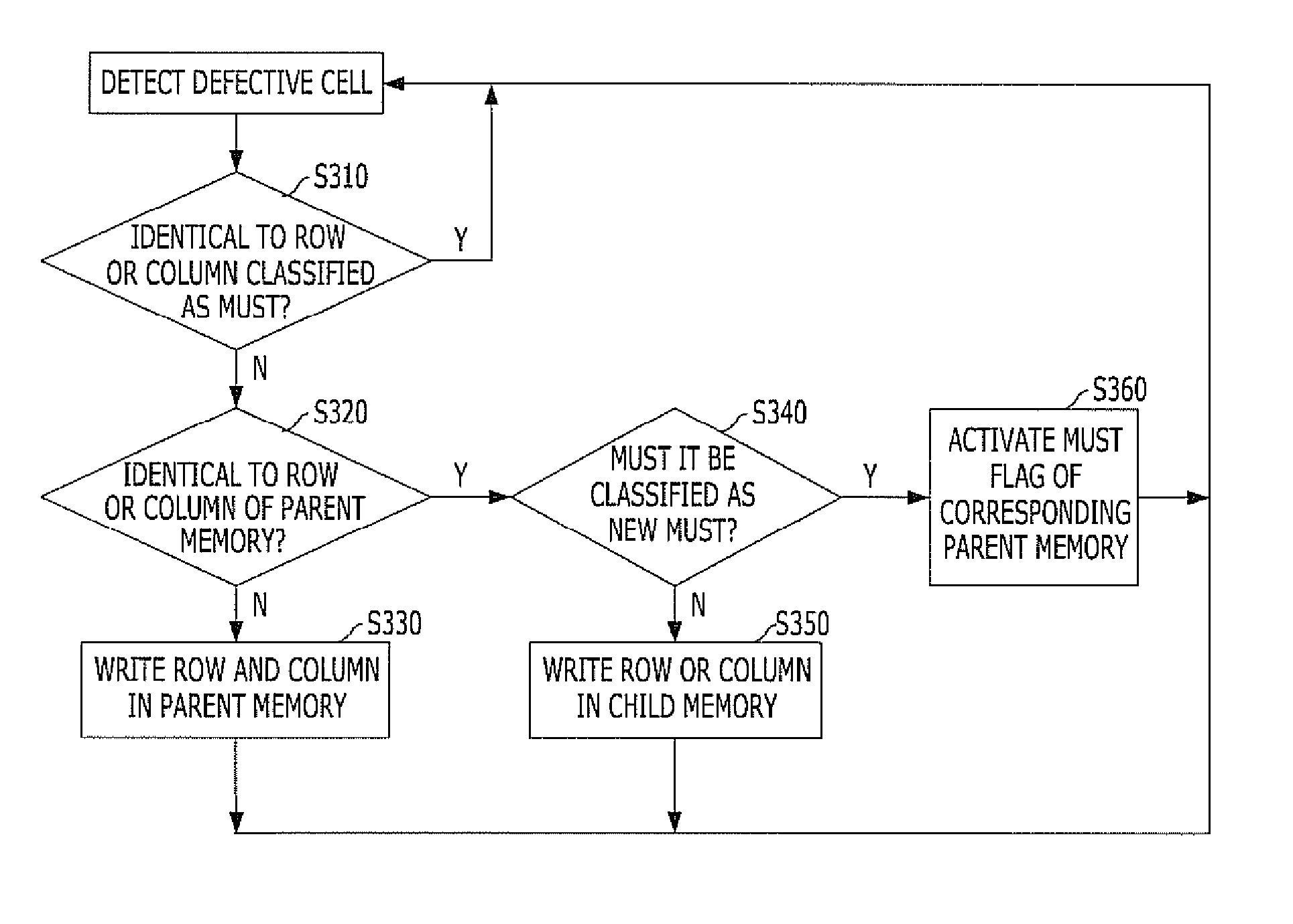
[0021]Exemplary embodiments of the present invention will be described below in more detail with reference to the accompanying drawings. The present invention may, however, be embodied in different forms and should not be construed as limited to the embodiments set forth herein. Rather, these embodiments are provided so that this disclosure will be thorough and complete, and will fully convey the scope of the present invention to those skilled in the art. Throughout the disclosure, like reference numerals refer to like parts throughout the various figures and embodiments of the present invention.

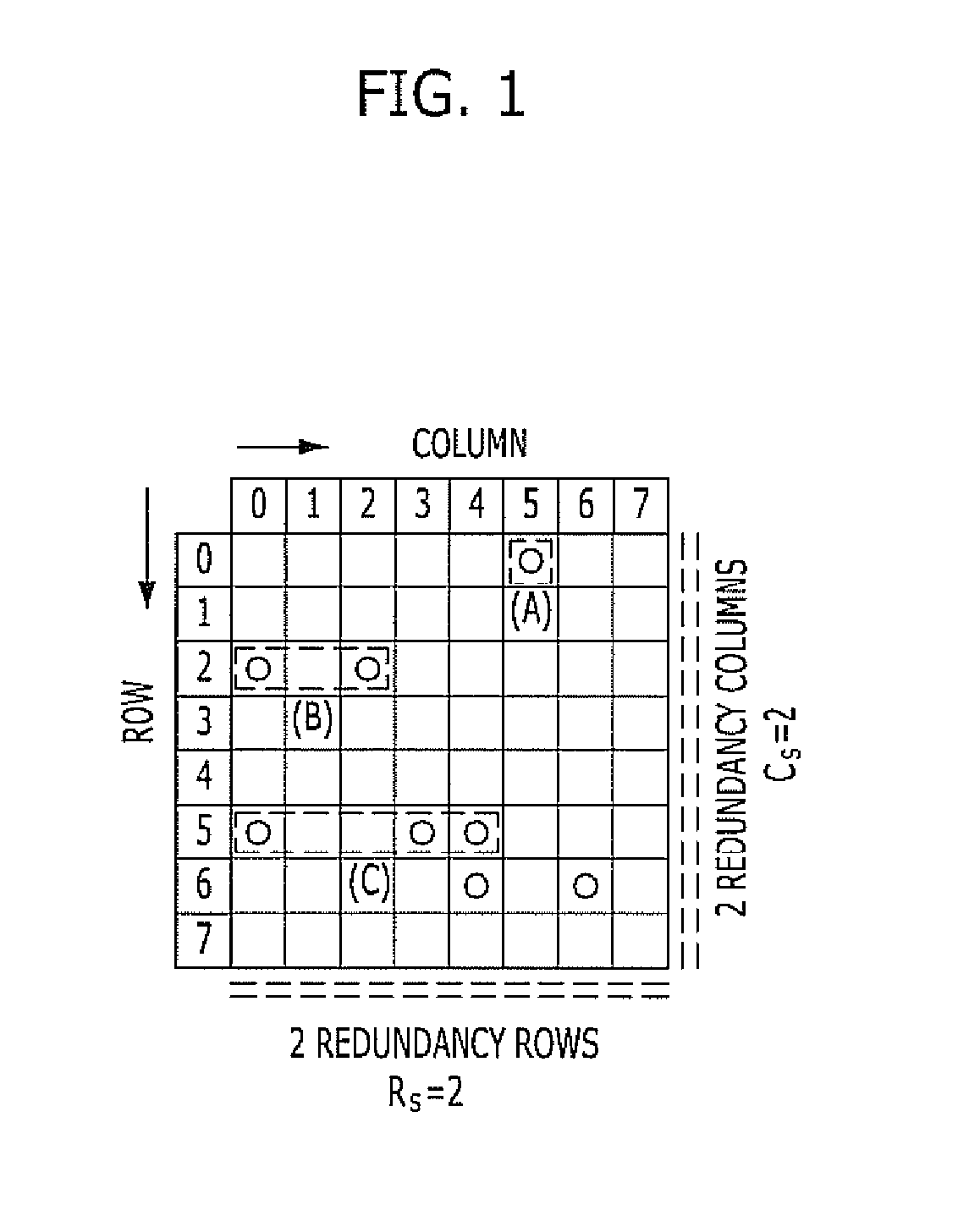
[0022]First, a repair rate and a fault classification method are described for a better understanding of the present invention.

[0023]A. Repair Rate

[0024]A repair rate is defined as Equation 1 below.

RepairRate=NumberofRepairedChipsNumberofRepairableChipsEq.1

[0025]The optimal repair rate is 100%. The repair rate becomes 100% if one or more solutions can be found for a repairable fault. In the ...


PUM


Abstract

A device for repair analysis includes a selection unit and an analysis unit. The selection unit is configured to select a part of the row addresses of a plurality of spare pivot fault cells and a part of the column addresses of the spare pivot fault cells in response to a control code. The analysis unit is configured to generate an analysis signal indicating whether row addresses of a plurality of non-spare pivot fault cells are included in selected row addresses and column addresses of the non-spare pivot fault cells are included in selected column addresses.

Description

CROSS-REFERENCE(S) TO RELATED APPLICATIONS[0001]The present application claims priority of Korean Patent Application No. 10-2010-0116823, filed on Nov. 23, 2010, which is incorporated herein by reference in its entirety.BACKGROUND OF THE INVENTION[0002]Exemplary embodiments of the present invention relate to semiconductor memory devices, and more particularly, to a repair analysis device and method for calculating a repair solution by using information about a fault cell detected in a memory device.[0003]In the early stage of semiconductor memory industry, a wafer with a larger number of original good semiconductor dies with no defective cell could be produced in a semiconductor fabrication process. However, as the memory capacity has increased, it has become difficult to fabricate a memory chip without any fault cell.[0004]Accordingly, a method for replacing a fault memory cell with a spare memory cell (i.e., a redundancy memory cell) has been proposed. In order to replace a fault ...

Claims


Application Information

Patent Timeline
IPC IPC(8): G11C29/04G06F11/22
CPCG11C29/4401G11C2029/1208G11C29/808G11C29/72
Inventor JEONG, WOO-SIKLEE, KANG-CHILCHO, JEONG-HOLEE, KYOUNG-SHUBKANG, IL-KWONKANG, SUNGHOLEE, JOO HWAN
Owner SK HYNIX INC
Learn More