
Electric junction box

a junction box and box body technology, applied in the direction of electrical apparatus casings/cabinets/drawers, coupling device connections, printed circuits, etc., can solve the problems of difficult insertion of cassette blocks, deterioration of box body rigidity, and time-consuming assembly, so as to achieve convenient assembly and reduce time

Active Publication Date: 2005-09-22
YAZAKI CORP
View PDF4 Cites 11 Cited by
  • Summary
  • Abstract
  • Description
  • Claims
  • Application Information

AI Technical Summary

Benefits of technology

[0014] It is therefore an objective of the present invention to solve the above problem and to provide an electric junction box, so that the cassette block, in which electrical components are mounted, can be easily inserted into the mounting hole of the box body.
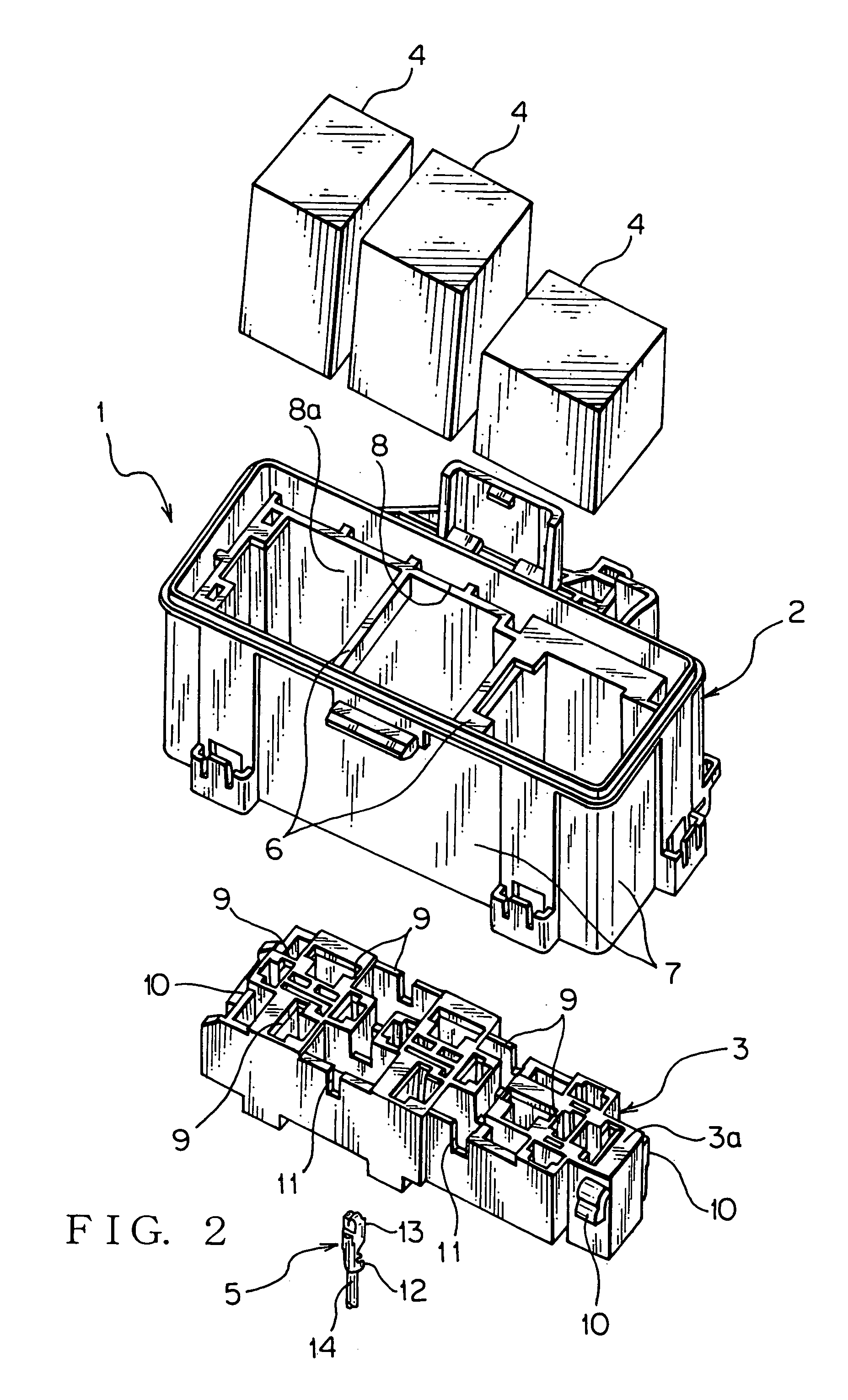
[0019] With the construction described above, one end of the rib continues to the one inner wall surface of the mounting hole while an opposite end of the rib continues to the opposite inner wall surface of the mounting hole. Therefore, the rigidity of the mounting hole, that is, the rigidity of the box body is improved so as to be hardly distorted, and the mounting hole is hardly distorted, that is, the box body is hardly distorted when the box body is molded. Since the box body is hardly distorted, therefore the cassette block, in which the electric components are mounted, can be easily mounted in the mounting hole.
[0021] With the construction described above, the rib is prevented from interfering with the electric components mounted in the cassette block. Therefore, the cassette block can be easily mounted in the mounting hole and the mounting hole can be made compact, that is, the box body can be made compact.
[0023] With the construction described above, the rib enters into the groove, thereby preventing the box body from being distorted after the cassette block is mounted, that is, preventing the electric junction box from being distorted after the cassette block is mounted. Further, since the rib enters into the groove, therefore the box body can be made compact, that is, the electric junction box can be made compact. The cassette block can be easily mounted in the mounting hole.
[0025] With the construction described above, the cassette block can be securely mounted in the box body after the electric components are mounted in the cassette block. Therefore, the electric junction box can be easily assembled with reducing time and man-hour for the assembly.

Problems solved by technology

Therefore, the assembly needs a lot of time and man-hour.
Therefore, if the number of the electrical components to be mounted in the cassette block is increased or the size of the electrical component is increased, the rigidity of the box body tends to deteriorate since the box body includes the mounting hole for receiving the cassette block.
Therefore, when the cassette block is inserted into the mounting hole, the box body is distorted, causing difficulty in the insertion of the cassette block into the mounting hole.
Moreover, since the box body is made of synthetic resin and molded by a known injection molding or the like, the box body might be distorted when the molded box body is subjected to injection molding or removed from a mold.
In such case, of course, the insertion of the cassette block into the mounting hole becomes difficult.

Method used


Image

  • Electric junction box
  • Electric junction box
  • Electric junction box

Examples


Embodiment Construction

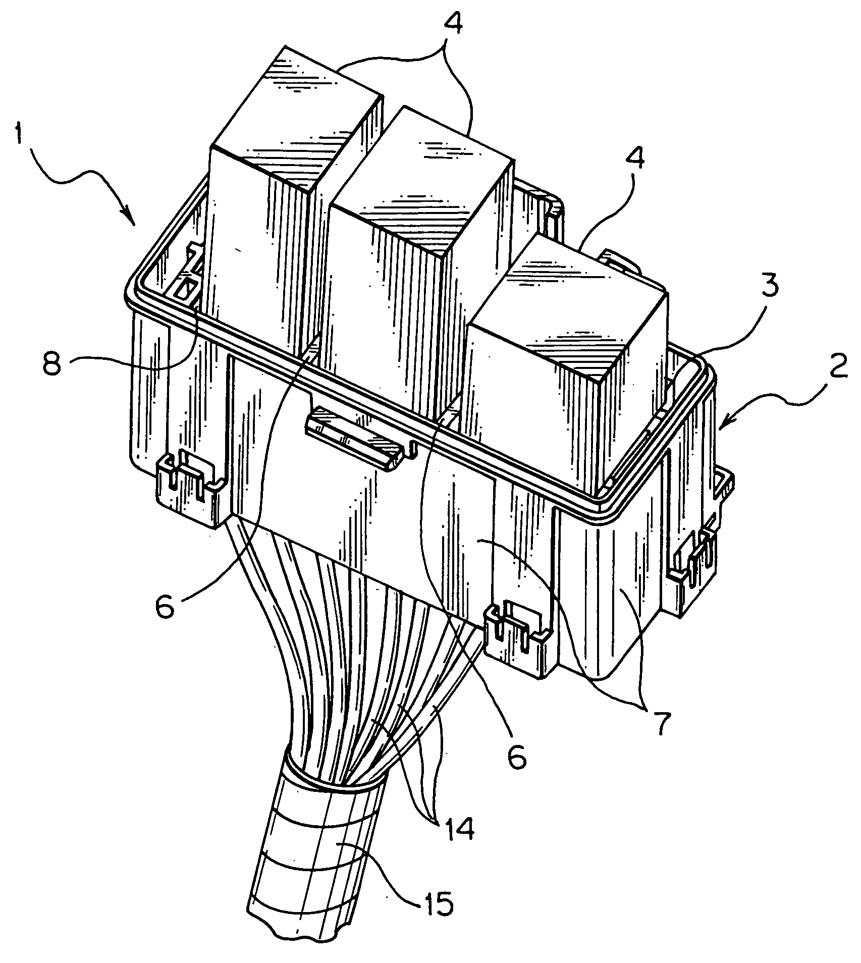
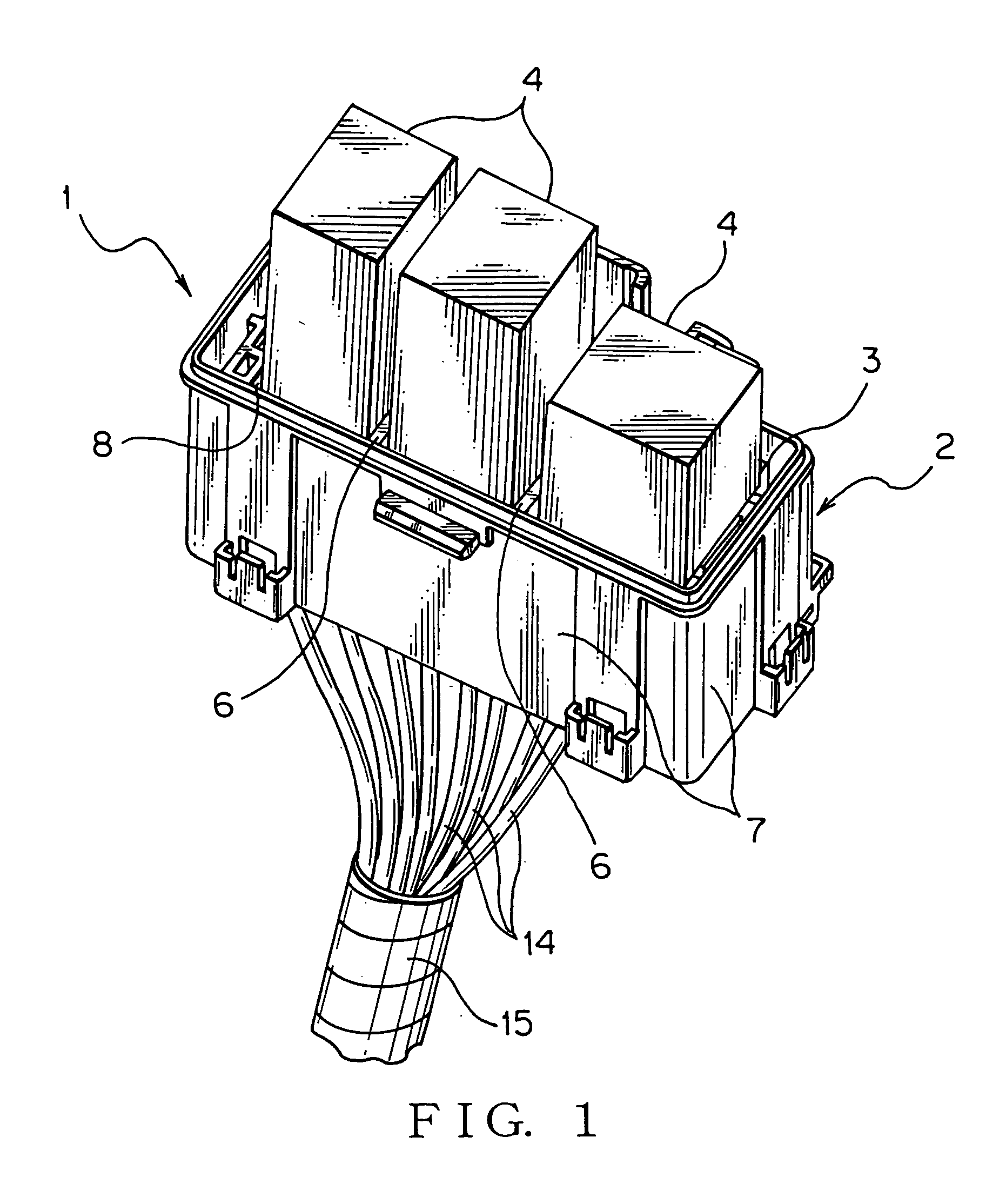
[0030] In the following, an electric junction box according to a preferred embodiment of the present invention will be explained with reference to FIGS. 1-4C. The electric junction box 1 shown in FIG. 1 is mounted on a motor vehicle as a mobile unit. As shown in FIGS. 1 and 2, the electric junction box 1 includes a box body 2, cassette block 3, a plurality of relays 4, a plurality of terminal fittings 5 (only one terminal fitting being shown only in FIG. 2), and a plurality of ribs 6.

[0031] The box body 2 is made of electrically insulating synthetic resin and molded by known injection molding. The box body 2 is formed in a tube-shape (box-shape) with a plurality of outer walls 7. The box body 2 is provided with a mounting hole 8. The mounting hole 8 is a space surrounded by a plurality of the outer walls 7 that construct the box body 2. Both ends situated at the top and bottom of the mounting hole 8 shown in FIGS. 1 and 2 are open. That is, the box body 2 is formed in a tube-shape ...


PUM


Abstract

The electric junction box includes a box body, cassette block, relay, terminal fitting and rib. The box body includes a mounting hole. A groove is formed hollow from a surface of the cassette block. The relay is mounted on the surface of the cassette block. The terminal fitting is received in the cassette block. The rib extends from one inner wall surface to an opposite inner wall surface of the mounting hole. The cassette block is received in the mounting hole of the box body. The rib enters into the groove.

Description

BACKGROUND OF THE INVENTION [0001] (1) Field of the Invention [0002] The present invention relates to an electric junction box, which is mounted on a motor vehicle and so on as a mobile unit. [0003] (2) Description of the Related Art [0004] Generally, various electronic equipment such as lamps such as a head lamp and tail lamp, and motors such as a starter motor and motor for an air-conditioner is mounted on a motor vehicle as a mobile unit. [0005] In order to supply electric power to various equipment described above, a junction block has been arranged on a suitable position in a motor vehicle. The junction block is constructed in such a manner that various electric circuit units, such as many fuses and relays, are put together. [0006] In this connection, since the junction block may includes fuses, relays and busbars therein, the junction block is sometimes called a fuse block, relay box or electric junction box as a generic name. In this specification, such a fuse block, relay bo...

Claims


Application Information

Patent Timeline
IPC IPC(8): H01R12/00H05K5/00H01R13/518H02G3/16
CPCH01R13/518
Inventor TAKEUCHI, KUNIHIKO
Owner YAZAKI CORP
Learn More