Load balancing in wireless communication network

Inactive Publication Date: 2005-09-22
NOKIA TECHNOLOGLES OY
View PDF5 Cites 153 Cited by
  • Summary
  • Abstract
  • Description
  • Claims
  • Application Information

AI Technical Summary

Benefits of technology

[0009] Accordingly, it is an object of the present invention to ach

Problems solved by technology

However, according to this conventional roaming procedure, a load situation in the wireless communication network is not considered in the decision for roaming.
In other words, a subscriber terminal could be switched or associated with an AP in which the load situation is such that the communication connection quality is not satisfying.
Thus, in conventional

Method used


Image

  • Load balancing in wireless communication network
  • Load balancing in wireless communication network
  • Load balancing in wireless communication network

Examples


Example

[0036] A first embodiment of the present invention is described with reference to FIGS. 1, 2 and 3.

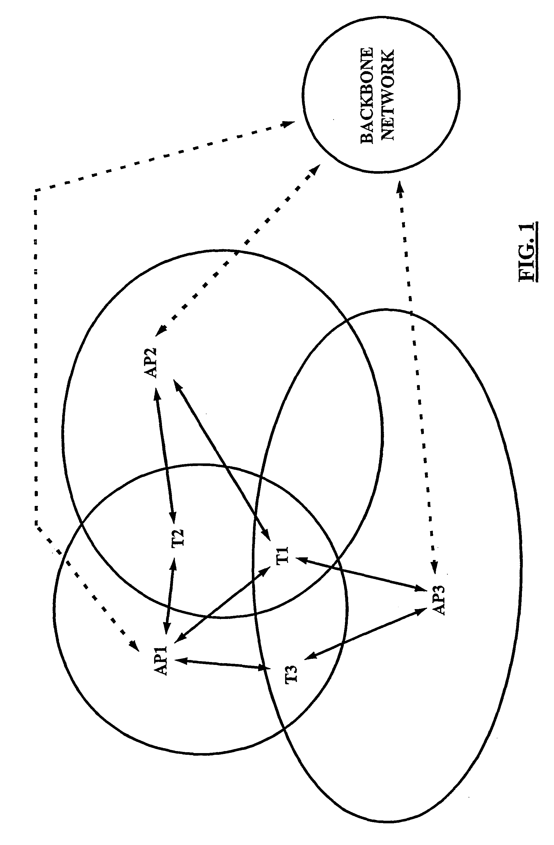
[0037] Referring to FIG. 1, a wireless communication network such as a WLAN comprises several access points AP1, AP2, AP3 as communication control elements. Furthermore, in the example shown, a backbone network is provided which serves as a distribution network for connecting the APs to one another and to external destination points such as other WLANs or fixed networks. For connecting the APs to the backbone network, commonly known input / output (I / O) interfaces are used.

[0038] Each of the APs defines a cell of a specific size (indicated by the circles surrounding the APs). Subscriber terminals T1, T2, T2 within the network may be associated (connected) with one AP (serving AP) in whose cell they are located. In the present example, as the starting situation, subscriber terminal T1 is associated with AP1, T2 is associated with AP2, and T3 is associated with AP3.

[0039] Irrespective o...

Example

[0066] Next, a second embodiment will be described with reference to FIGS. 4 to 7.

[0067] It is to be noted that some of the means, functionality and procedures of the second embodiment are parallel to corresponding means, functionality and procedures of the first embodiment. Thus, a repetition of a detailed description thereof is omitted.

[0068]FIG. 4 shows a wireless communication network such as a WLAN comprising several access points AP1, AP2, AP3 as communication control elements, a backbone network as a distribution network for connecting the APs to one another and to external destination points such as other WLANs or fixed networks. Furthermore, a separate network element 100 is provided which comprises a load control device (LC) 110. The separate network element 100 is connected to the access points by the backbone network for exchanging data.

[0069] Subscriber terminals T1, T2, T2 located in cells defined by the access points AP1, AP2, AP3 may be associated (connected) with...


PUM


Abstract

For load balancing in a wireless communication network comprising at least one subscriber terminal (T1, T2, T2) and a plurality of access points (AP1, AP2, AP3), a load control device (21; 110) is used which is located outside of said subscriber terminal, wherein said load control device is adapted to process information related to a load in said wireless communication network and to instruct roaming of said subscriber terminal from an associated access point to another one of said plurality of access points. Access point status information (APST) determined in said plurality of access points (S10; S110) is received and communication status information related to said plurality of access points (S20; S120) is determined. The subscriber terminal processes (S20; S120) these information into roaming support information (RSUP), which are in turn processed (S40; S160) in said load control device an access point related load based roaming analysis. On this basis, it is decided (S50; S170) by the load control device, whether said subscriber terminal is to be associated with another one of said plurality of access points.

Description

FIELD OF THE INVENTION [0001] The present invention relates to a method for load balancing in a wireless communication network, a corresponding system, a load control device, a corresponding access point usable in a wireless communication network, a corresponding network element usable in a wireless communication network, a corresponding subscriber terminal usable in a wireless communication network and a computer program product for implementing the method for load balancing in a wireless communication network. BACKGROUND OF THE INVENTION [0002] In the last years wireless communication networks, for example for data and / or speech transmissions, became more and more important. One example for such a wireless communication network is a wireless local area network (WLAN), independent of a radio frequency or the like (infrared etc.) used for this network. In such a WLAN, subscriber terminals, such as personal computers, telecommunication equipments, mobile phones, personal digital assi...

Claims


Application Information

Patent Timeline
IPC IPC(8): H04L12/28H04L12/801H04L12/803H04W28/08H04W48/06H04W48/10H04W48/20
CPCH04L47/125H04L47/14H04W48/20H04W48/06H04W48/10H04W28/08H04W28/0205H04W28/0861H04W8/04
Inventor HASSE, SINIVAARA
Owner NOKIA TECHNOLOGLES OY
Why Eureka
Try Eureka