Bifurcation stent delivery devices

Inactive Publication Date: 2005-09-22
Y MED
View PDF21 Cites 104 Cited by
  • Summary
  • Abstract
  • Description
  • Claims
  • Application Information

AI Technical Summary

Benefits of technology

[0022] The present invention successfully addresses the shortcomings of the presently known configurations by providi

Problems solved by technology

Several problems are associated with known prior art bifurcation stent delivery devices.
The relatively large profiles of currently known systems cause difficulties in maneuverability and access to the site.
Furthermore, the presence of two guidewires often results in wire entanglement, making the procedure difficult to perform without multiple insertions and retractions.
Another problem which persists in these devices is inaccurate positioning within the vessel.
As such, inaccurate deployment is commonplace, often resulting in either stent jailing or insufficient coverage.
Furthermore, the presence of two wires can lead to problems of wire entanglement.
Ho

Method used


Image

  • Bifurcation stent delivery devices
  • Bifurcation stent delivery devices
  • Bifurcation stent delivery devices

Examples


first embodiment

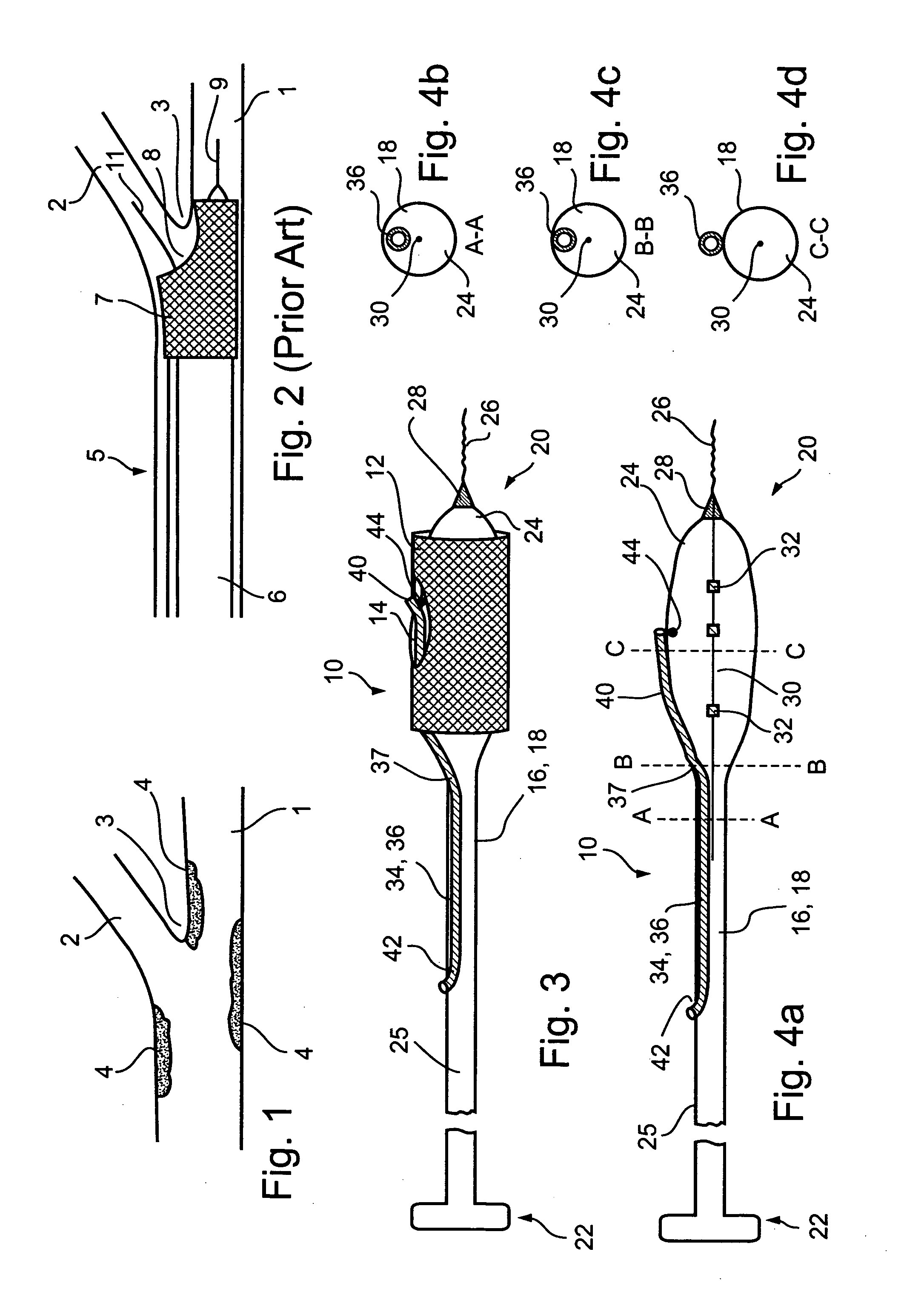
[0055] In a first embodiment, a stent delivery system 10 is designed to be delivered at a bifurcation, such as the one illustrated in FIG. 1, having a main vessel 1 and a branch vessel 2, wherein the plaque 4 is located within the main vessel in the vicinity of bifurcation point 3.

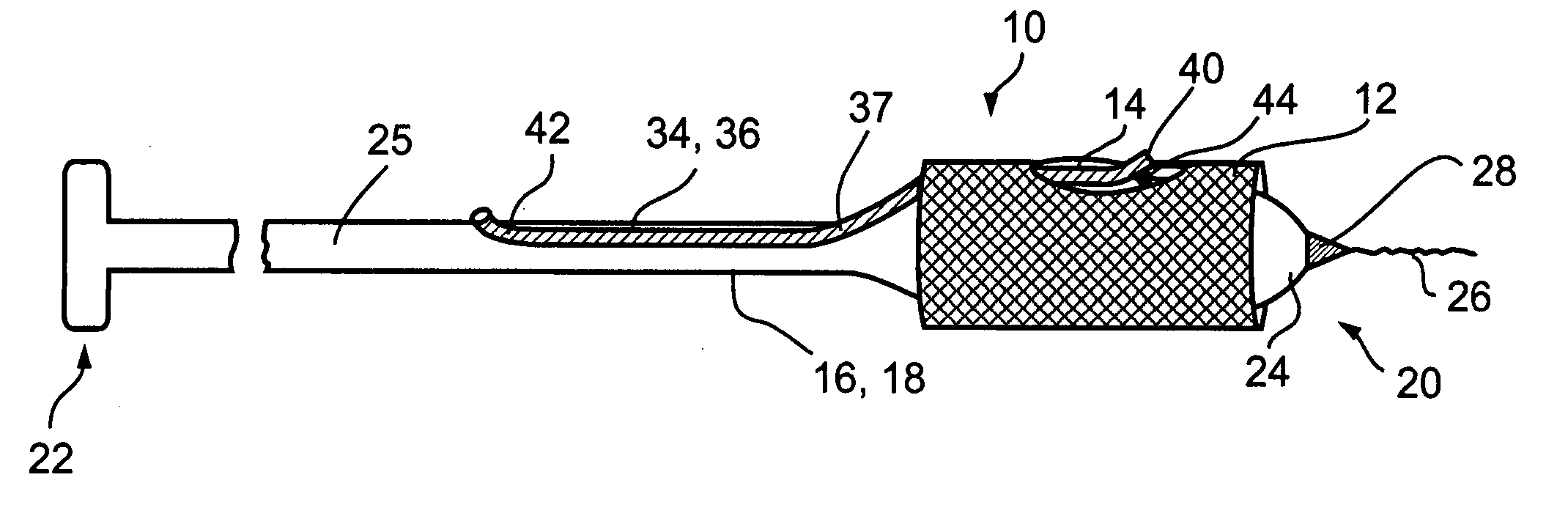
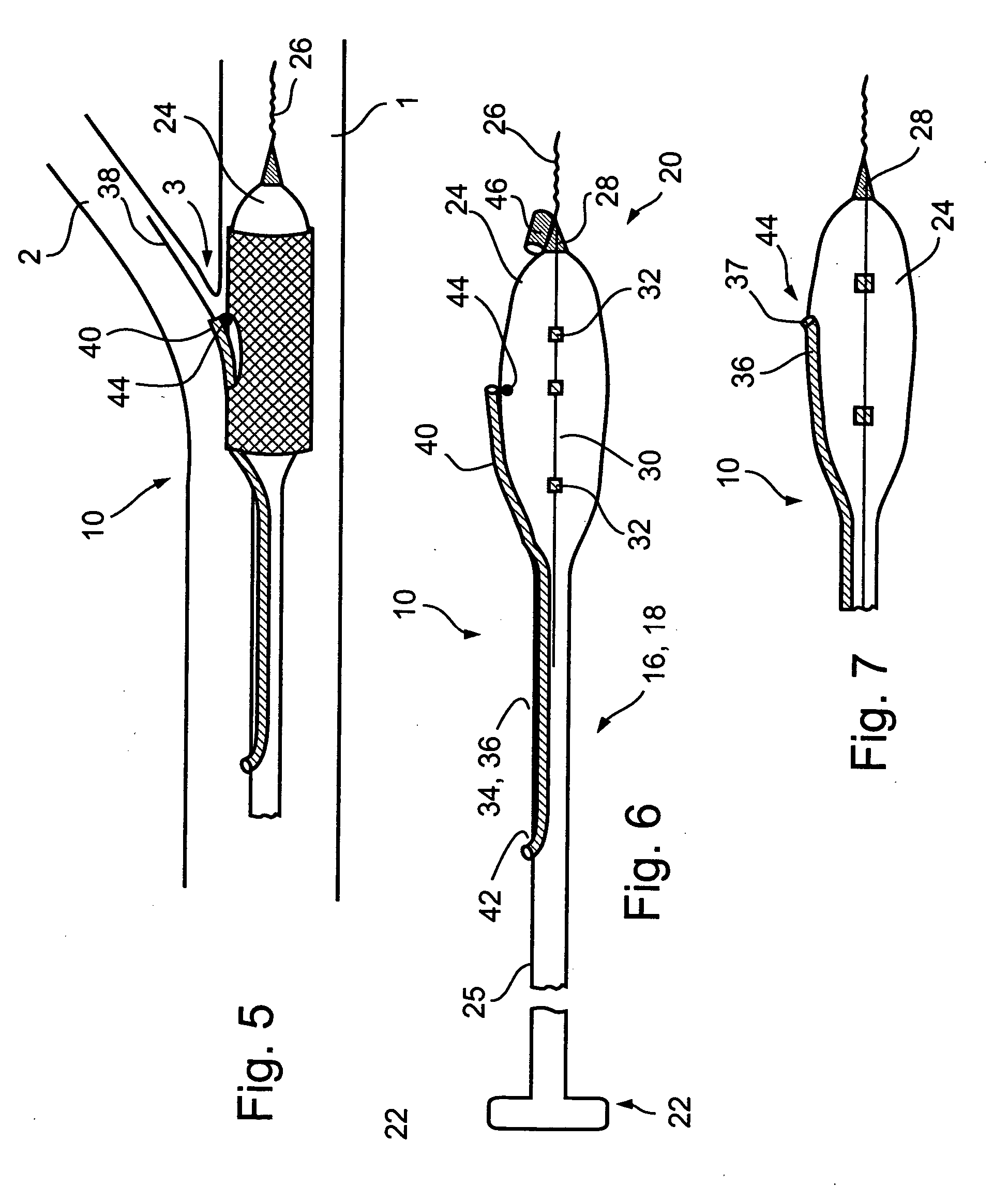
[0056] Reference is now made to FIG. 3 and FIGS. 4a-d, which are illustrations of a bifurcation stent delivery system 10, shown with and without a stent respectively. System 10 includes a main elongated element 16, and an auxiliary elongated element 34 aligned with main elongated element 16. In a preferred embodiment, auxiliary elongated element 34 is positioned within main elongated element 16 proximal to an exit point 37 and alongside main elongated element 16 distal to exit point 37, as depicted in FIG. 3. In an alternative embodiment, auxiliary elongated element 34 is positioned alongside main elongated element 16, as will be described hereinbelow with reference to FIG. 8.

[0057] In a preferred embodim...

second embodiment

[0070] In a second embodiment, a stent delivery system 110 is designed to be delivered at a bifurcation as illustrated in FIG. 10, having a main vessel 1 and a branch vessel 2 at an angle with respect to main vessel 1, and wherein plaque 4 is located in main vessel 1 at an area of a bifurcation 3. One example of such a location is the coronary artery, where blockage of, for example, the left anterior descending (LAD) artery is to be avoided while providing coverage to the plaque within the coronary artery. Other examples include renal arteries, the left main coronary artery, vein grafts, and others.

[0071] Reference is now made to FIGS. 11a-c, which are illustrations of different embodiments of a system 110 for delivery of a stent at a bifurcation such as the one depicted in FIG. 10. System 110 may be designed with a fixed wire, as shown in FIG. 11a, as on over-the-wire system, as shown in FIG. 11b, or as a rapid exchange system, as shown in FIG. 11c.

[0072] Reference is now made to ...

third embodiment

[0077] In a third embodiment, a stent delivery system 210 is designed to be delivered at a bifurcation such as the one illustrated in FIG. 13, having a main vessel 1 and a branch vessel 2 at an angle with respect to main vessel 1, and wherein plaque 4 is located in branch vessel 2 at an area of a bifurcation 3. In an exemplary preferred embodiment, main vessel 1 is an aorta.

[0078] Reference is now made to FIGS. 14a and 14b, which are views of a system 210 in accordance with an embodiment of the present invention. System 210 includes a main elongated element 216 and an auxiliary elongated element 234. In a preferred embodiment, main elongated element 216 is a catheter 218 having a proximal end 222 and a distal end 220. Catheter 218 has a balloon 224 at distal end 220, with a stent 212 positioned thereon. In one embodiment, balloon 224 includes a main guidewire lumen 227. In an alternative embodiment, balloon 224 is a fixed wire balloon, such as described with reference to the first a...


PUM


Abstract

A stent delivery system for treating bifurcations is provided. The system has a low profile and provides substantially predictable translational and rotational positioning. In one embodiment, the system includes a fixed wire balloon catheter and a partially attached side branch lumen, wherein the side branch lumen is attached to the catheter at a crotch point. The location of the crotch point is predetermined so as to provide substantially predictable positioning. Several embodiments of the system are described for various types of bifurcations and vessels.

Description

[0001] This application claims the benefit of U.S. Provisional Application No. 60 / 549,554, filed on Mar. 4, 2004, incorporated herein by reference in its entirety.FIELD AND BACKGROUND OF THE INVENTION [0002] The present invention relates to stent delivery devices and methods and, more particularly, to stent delivery devices for positioning at a bifurcation, the devices having low profiles and predictable positioning capabilities, both rotationally and translationally. [0003] Several problems are associated with known prior art bifurcation stent delivery devices. First, they generally have large outer diameters, particularly since the known designs usually include two guidewire lumens—one for a main guidewire and one for a side branch guidewire. The relatively large profiles of currently known systems cause difficulties in maneuverability and access to the site. Furthermore, the presence of two guidewires often results in wire entanglement, making the procedure difficult to perform w...

Claims


Application Information

Patent Timeline
IPC IPC(8): A61F2/06
CPCA61F2/856A61F2/954A61F2/958A61F2002/065A61M2025/1056A61F2250/006A61M25/1011A61M2025/0186A61M2025/1045A61F2250/0039
Inventor SHAKED, YOAV
Owner Y MED
Why Eureka
Try Eureka