
Load balancing method and system

Inactive Publication Date: 2005-09-22
KUMAGAI ATSUYA +3
View PDF17 Cites 38 Cited by
  • Summary
  • Abstract
  • Description
  • Claims
  • Application Information

AI Technical Summary

Benefits of technology

[0003] Incidentally, as a SAN (Storage Area Network) in which a server and a storage system, are connected by a dedicated network, an FC SAN, in which a SAN is constituted by a fiber channel, has been mainly used. However, recently, an IP SAN, in which a SAN is constituted by an IP (Internet Protocol) network is being widespread. The IP SAN has advantages compared with the FC SAN. for example, the IP SAN can be realized at lower cost than the FC SAN.

Problems solved by technology

Note that the congestion means that relay and transmission of a packet cannot be performed due to generation of a packet exceeding a processing capability of a forwarding device or a reception side.
It is likely that continuous decline in a throughput is caused by the reduction of the window size.

Method used


Image

  • Load balancing method and system
  • Load balancing method and system
  • Load balancing method and system

Examples


first embodiment

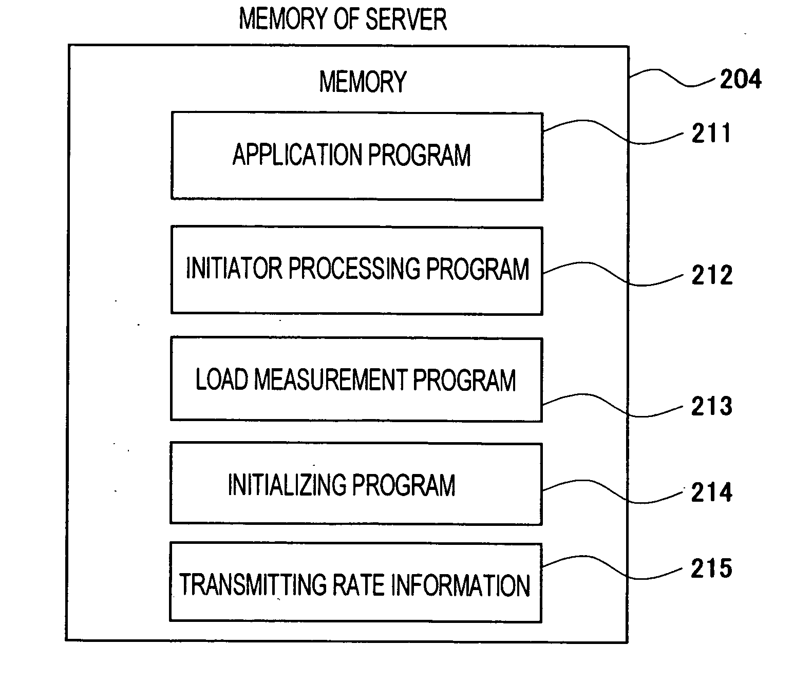
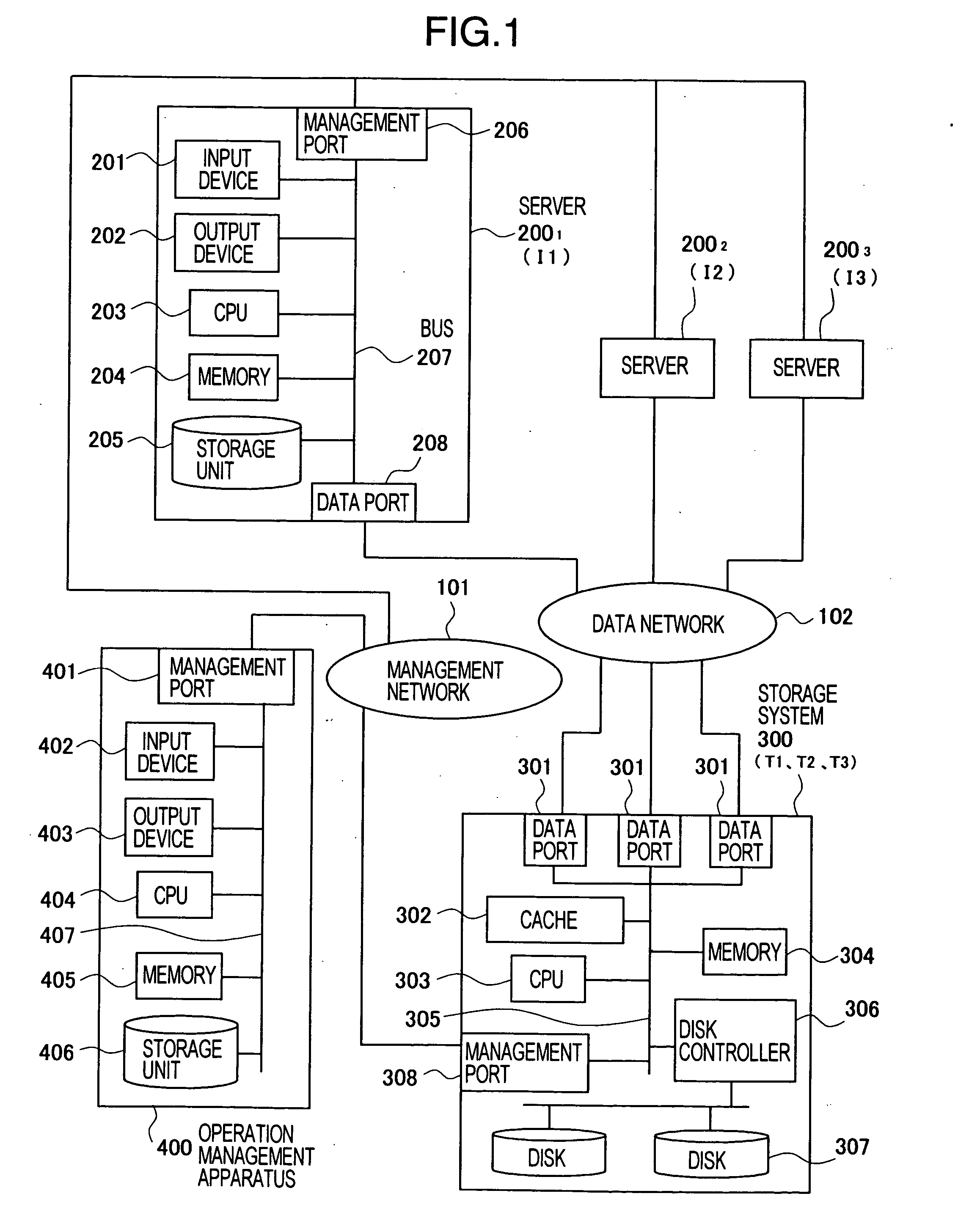
[0034] In a first embodiment, a case in which servers 200 writes data in a storage system 300 using an iSCSI protocol will be described as an example. Note that the iSCSI protocol is a protocol for transmitting and receiving an SCSI command (a write request or a read request) and data, which are used for communication between a storage unit and a computer, through an IP network. In the iSCSI protocol, the computer system is constituted by iSCSI initiators which issue the SCSI command to request processing, and iSCSI targets which perform the processing. In this embodiment, the servers 200 include the iSCSI initiators, and the storage system 300 includes the iSCSI targets.

[0035] In addition, in the iSCSI protocol, the SCSI command and the data are subjected to encapsulation processing to create an iSCSI PDU (Protocol Data Unit). The iSCSI PDU is a unit of data to be treated by the iSCSI protocol. Further, in the iSCSI protocol, the iSCSI PDU is divided into several packets and sent v...

second embodiment

[0117] it is unnecessary to allocate a transmitting rate to a combination of an iSCSI initiator and an iSCSI target, which do not perform write processing, in advance. Thus, it is made possible to allocate a larger transmitting rate to other combinations of iSCSI initiators and iSCSI targets.

[0118] Next, a third embodiment will be described. In the first and the second embodiments, the method of controlling a transmitting rate of the data server port 208 in the processing for writing data from the server 200 to the storage system 300 is described. In this embodiment, an embodiment for controlling a transmitting rate of the data storage ports 301 in the case in which the server 200 reads data from the storage system 300 will be described.

[0119] A configuration of a computer system to which this embodiment is applied is the same as that in the first embodiment shown in FIGS. 1 to 8 except the points described below. First, programs and data stored in the memory 304 of the storage sy...

third embodiment

[0140] A configuration of a computer system to which this embodiment is applied is the same as that in the third embodiment except the points described below.

[0141]FIG. 20 is a schematic diagram or the computer system to which the fourth embodiment of the present invention is applied. As shown in the figure, the computer system of this embodiment includes a server 200, a storage system 300, an operation management apparatus 400, a data network 102, a management network 101, and a source storage system 2000. Configurations of the apparatuses other than the source storage system 2000 of this computer system are the same as these shown in FIG. 1 to which the third embodiment is applied. The source storage system 2000 receives a write request for data from the server 200 and stores write data in the disk 307. Then, for backup at the time of failure or the like, the source storage system 2000 remotely copies the write data received from the server 200 to the storage system 300 via the da...


PUM


Abstract

A load balancing method includes a measurement step of measuring reception loads of respective storage ports 301 provided in a storage system 300; an allocation changing step of changing a transmitting rate of a computer port 208 provided in a computer 200, which is allocated for each of the storage ports, on the basis of the reception loads of the respective storage ports 301 measured in the measurement step; and a transmission step of transmitting data to the respective storage ports 301 of the storage system 300 at a transmitting rate in a range not exceeding the transmitting rate for each of the storage ports 301 changed in the allocation changing step.

Description

BACKGROUND OF THE INVENTION [0001] The present invention relates to a technique for load balance in a computer system, and in particular to a technique for load balance of ports in a storage system. [0002] Japanese Patent Laid-open Publication No. H7-334449 (hereinafter referred to as Patent Document 1) discloses a technique for performing load balance of ports in a storage system including plural ports. In other words, loads at the respective ports in the storage system are measured, and a port with a low load is selected on the basis of a result of the measurement to input and output data. SUMMARY OF THE INVENTION [0003] Incidentally, as a SAN (Storage Area Network) in which a server and a storage system, are connected by a dedicated network, an FC SAN, in which a SAN is constituted by a fiber channel, has been mainly used. However, recently, an IP SAN, in which a SAN is constituted by an IP (Internet Protocol) network is being widespread. The IP SAN has advantages compared with t...

Claims


Application Information

Patent Timeline
IPC IPC(8): G06F3/06G06F12/00G06F13/10G06F15/16G06F15/173H04L29/08
CPCH04L67/1002H04L67/1008H04L67/1001
Inventor KUMAGAI, ATSUYASHIGA, KENTAIWAMI, NAOKOHONDA, KIYOSHI
Owner KUMAGAI ATSUYA
Features
  • Generate Ideas
  • Intellectual Property
  • Life Sciences
  • Materials
  • Tech Scout
  • Unparalleled Data Quality
  • Higher Quality Content
  • 60% Fewer Hallucinations
Learn More