Hydraulic valve actuation systems and methods to provide multiple lifts for one or more engine air valves

a technology of hydraulic valves and air valves, applied in the direction of machines/engines, non-mechanical valves, valve arrangements, etc., can solve the problems of not providing the accuracy and uniformity of valve lifts desired for smooth engine operation under all conditions, and a fixed relationship between crankshaft angle and valve position

Active Publication Date: 2005-09-29
STURMAN INDS
View PDF21 Cites 11 Cited by
  • Summary
  • Abstract
  • Description
  • Claims
  • Application Information

AI Technical Summary

Problems solved by technology

While such systems are in a high state of development and usually provide reliable performance for the life of the engine, they have the disadvantage of providing a fixed relationship between crankshaft angle and valve position.
Accordingly, the timing for valve opening and closing, the valve lift obtained, etc., are predetermined and fixed throughout the operating range of the engine, thus providing a substantial engine performance compromise under most engine operating conditions.
This, in theory, provides the desired result, though in practice may not provide the accuracy and uniformity in valve lift desired for smooth engine operation under all conditions.
This has certain advantages, but also adds to the complexity of the system.

Method used


Image

  • Hydraulic valve actuation systems and methods to provide multiple lifts for one or more engine air valves
  • Hydraulic valve actuation systems and methods to provide multiple lifts for one or more engine air valves
  • Hydraulic valve actuation systems and methods to provide multiple lifts for one or more engine air valves

Examples


Embodiment Construction

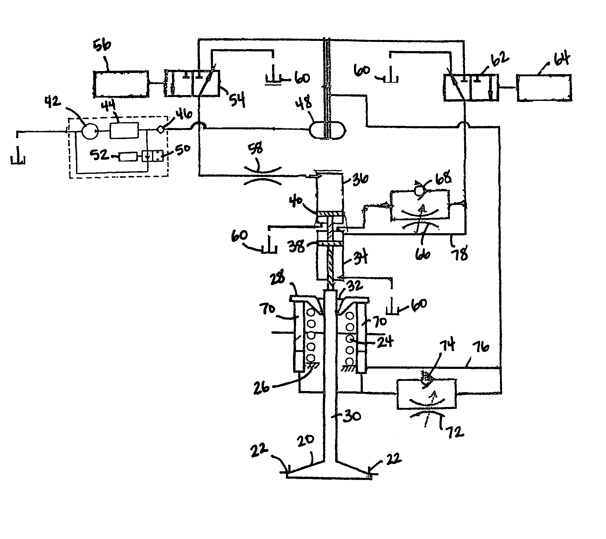
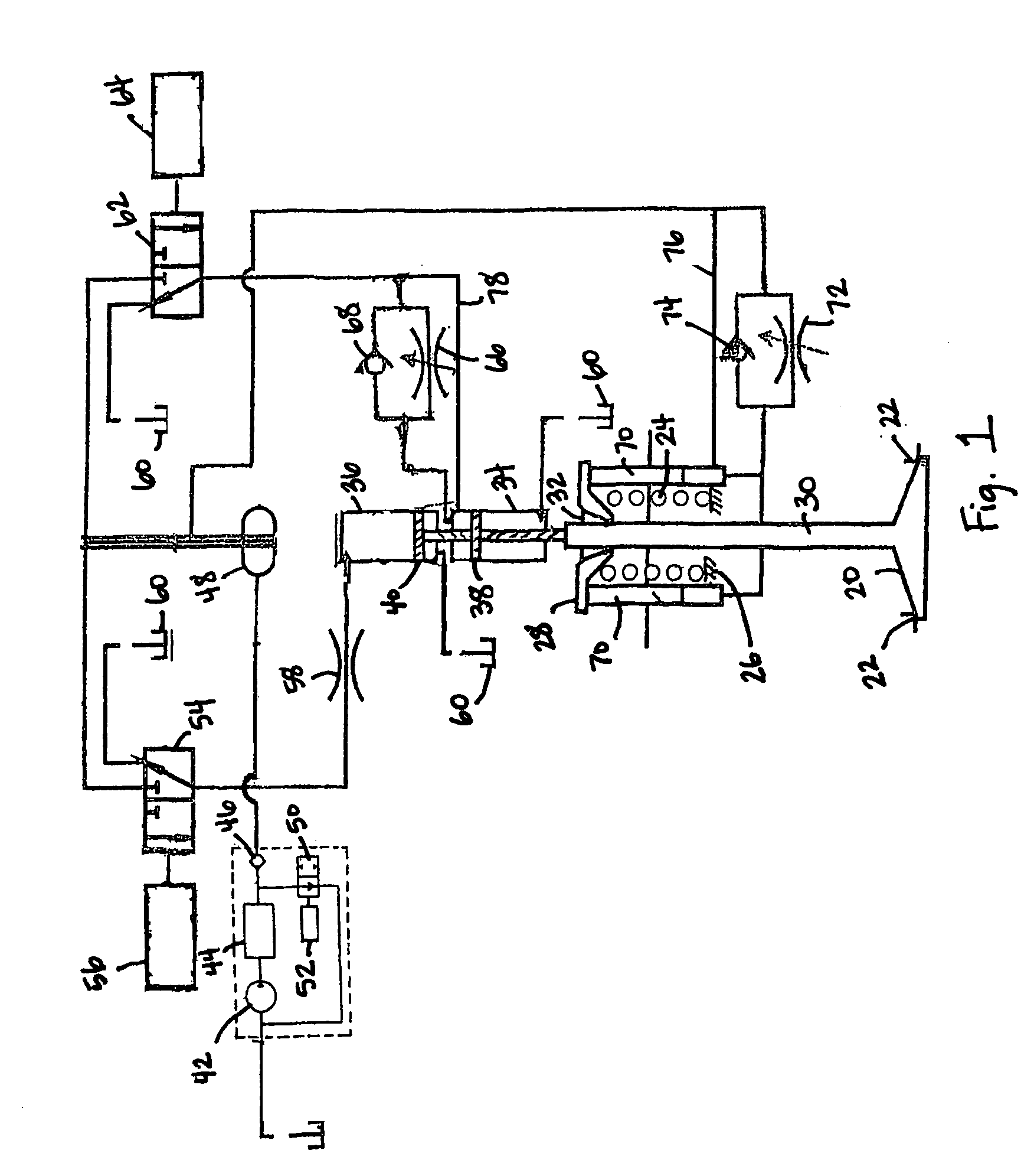
[0016] One aspect of the present invention is an engine valve hydraulic actuation system allowing a selection of valve lifts, each being determined by a fixed stop, thereby providing excellent repeatability in valve lift. Another aspect of the present invention provides hydraulic deceleration or braking of engine valve velocity, not only on engine valve closure but also at attainment of higher lift or lifts. Thus, by way of example, in a diesel engine while idling or when running at low load and low rpm, the intake valve or valves, or intake and exhaust valves, may be operated with the lower lift, thereby providing adequate aspiration while at the same time reducing the hydraulic energy used for engine valve actuation. By way of another example, in engines having multiple intake valves such as two per cylinder, one intake valve might be opened to a high lift and the other intake valve opened to a low lift to increase turbulence within the combustion chamber for better mixing of the ...


PUM


Abstract

Hydraulic valve actuation systems and methods to provide multiple lifts for engine valves using fixed or hard stops at each lift. The fixed or hard stops provide a very repeatable selection of engine valve lifts dependent on engine operating conditions. For full valve lift, unidirectional hydraulic dashpots are used to decelerate the engine valve, both as it approaches the full lift fixed stop, and as the engine valve approaches the valve seat from the engine valve full lift position. Various embodiments and methods of operation are disclosed.

Description

CROSS-REFERENCE TO RELATED APPLICATION [0001] This application claims the benefit of U.S. Provisional Patent Application No. 60 / 553,325 filed Mar. 15, 2004.BACKGROUND OF THE INVENTION [0002] 1. Field of the Invention [0003] The present invention relates to the field of piston engines. [0004] 2. Prior Art [0005] Historically, piston engines have used mechanically actuated poppet type intake and exhaust valves operated by way of an engine driven camshaft. While such systems are in a high state of development and usually provide reliable performance for the life of the engine, they have the disadvantage of providing a fixed relationship between crankshaft angle and valve position. Accordingly, the timing for valve opening and closing, the valve lift obtained, etc., are predetermined and fixed throughout the operating range of the engine, thus providing a substantial engine performance compromise under most engine operating conditions. [0006] More recently, considerable work has been do...

Claims


Application Information

Patent Timeline
Patent Type & Authority Applications(United States)
IPC IPC(8): F01L9/10F01L1/34
CPCF01L9/02F01L9/10
Inventor KLOSE, CHARLES CONRADSTRAUSS, RANDALL JAMESSTURMAN, ODED EDDIEPENA, JAMES A.
Owner STURMAN INDS
Why Eureka
Try Eureka