
Pump rod clamp and blowout preventer

a technology of clamping and clamping rods, which is applied in the direction of valve operation/release devices, valve details, fluid removal, etc., can solve the problems of increasing equipment costs, unable to meet the needs of use, and not without limitations, so as to improve the ability to clamp or grip, prevent or retard axial and/or rotational movement, and improve the effect of clamping or gripping ability

Active Publication Date: 2005-09-29
MILLENNIUM OILFLOW SYST & TECH
View PDF22 Cites 14 Cited by
  • Summary
  • Abstract
  • Description
  • Claims
  • Application Information

AI Technical Summary

Benefits of technology

[0007] The invention therefore provides a pump rod clamp and blowout preventer that is in the form of a single component capable of both sealingly engaging a polished rod to prevent the escape of fluid from a well, while at the same time providing an enhanced ability to clamp or grip the rod and to prevent or retard axial and / or rotational movement. In one embodiment the invention further provides a mechanism by which the polished rod may be clamped and securely held without scoring or damaging the exterior surface of the rod, and without the formation of an electrical bonding between the invention and the pump rod.
[0009] In a further aspect the invention provides a pump rod clamp for gripping a pump rod in an oil, gas or water well, the pump rod clamp comprising a central housing having a longitudinal bore for receiving a pump rod, said central housing including at least one pair of opposed radial bores generally perpendicular to said longitudinal bore and having interior ends terminating at said longitudinal bore; a ram received within each of said opposed radial bores, each of said rams having a leading face generally directed toward the exterior surface of the pump rod; and, one or more actuators to cause said rams to be moved within said opposed radial bores between an activated position where said rams grippingly engage the pump rod to limit rotational and axial movement thereof, and a deactivated position where said rams are disengaged from the pump rod, each of said rams including one or more gripping inserts releasably securable to their leading faces such that when said rams are in said activated position said gripping inserts contact the exterior surface of the pump rod, said gripping inserts having outer faces with an arcuate shape generally corresponding to the curvature of the exterior of the pump rod and coated with a ceramic material, said ceramic material enhancing the ability of said gripping inserts to grippingly engage the pump rod and providing an electrically insulative barrier between said pump rod clamp and the pump rod when said clamping members are in said activated position.
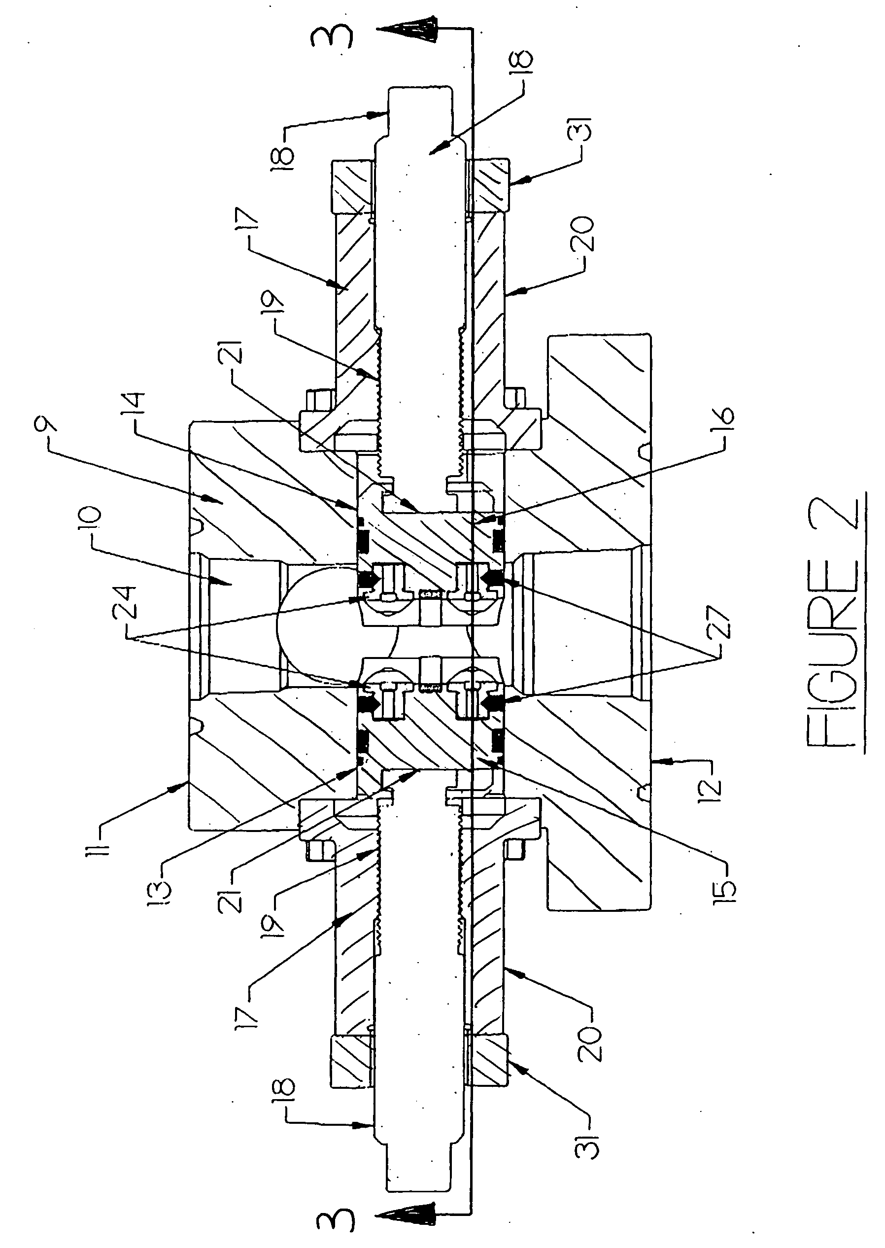
[0010] The invention also concerns a clamping blowout preventer for gripping a pump rod in an oil, gas or water well, the clamping blowout preventer comprising a central housing having a longitudinally oriented bore for receiving a pump rod, said central housing including at least two radially opposed bores generally perpendicular to said longitudinal bore and having interior ends terminating at said longitudinal bore; a ram received within each of said radially opposed bores, each of said rams having a leading face generally directed toward the exterior surface of the pump rod, said leading faces of said rams including one or more gripping inserts releasably secured thereto; at least one actuator to cause said rams to be moved between an activated and deactivated position, when in said activated position said rams driven inwardly toward the pump rod causing said gripping inserts to grippingly engage the exterior surface of the pump rod and to limit axial and rotational movement thereof, when in said deactivated position said rams retracted from the pump rod permitting said gripping inserts to be released from engagement with the pump rod; and, a seal secured to each of said rams such that the seals on opposed rams engage both the exterior surface of the pump rod and one another when said rams are in said activated position, to limit well fluids from escaping from the well.
[0011] In yet a further aspect the invention provides a pump rod clamp for gripping a pump rod in a oil, gas or water well, the pump rod clamp comprising central housing having a longitudinal bore for receiving a pump rod; a plurality of clamping members received within said central housing; and, one or more actuators to cause said clamping members to be moved between an activated position where they grippingly engage the exterior surface of the pump rod and a deactivated position where they are released from contact with the exterior surface of the pump rod, each of said clamping members comprising a ram received within a radial bore extending through said central housing generally perpendicular to said longitudinal bore and having an interior end terminating at said longitudinal bore, each of said rams having a leading face with an arcuate channel thereon for grippingly engaging the pump rod when said rams are in said activated position, said arcuate channel coated with a ceramic material to enhance the ability of said arcuate channel to grippingly engage the pump rod and to provide an electrically insulative barrier between said pump rod clamp and the pump rod when said rams are in said activated position.

Problems solved by technology

While currently available blowout preventers are generally effective in sealing around a polished rod and preventing the contents of a well from escaping, they nevertheless suffer from a number of inherent limitations.
Further, when the metallic faces of the rams contact the exterior of the polished rod an electrical connection will be formed therebetween, which in some circumstances may also be undesirable.
Currently available polished rod clamps are also not without their limitations.
Use of a dedicated rod clamp also results in an increase in equipment cost and represents a further mechanical component that may malfunction or fail.
In addition, the use of a separate polished rod clamp does not prevent an operator from over tightening the BOP rams and causing their metal faces to score or damage the surface of the polished rod.

Method used


Image

  • Pump rod clamp and blowout preventer
  • Pump rod clamp and blowout preventer
  • Pump rod clamp and blowout preventer

Examples


Embodiment Construction

[0028] The present invention may be embodied in a number of different forms. However, the specification and drawings that follow describe and disclose only some of the specific forms of the invention and are not intended to limit the scope of the invention as defined in the claims that follow herein.

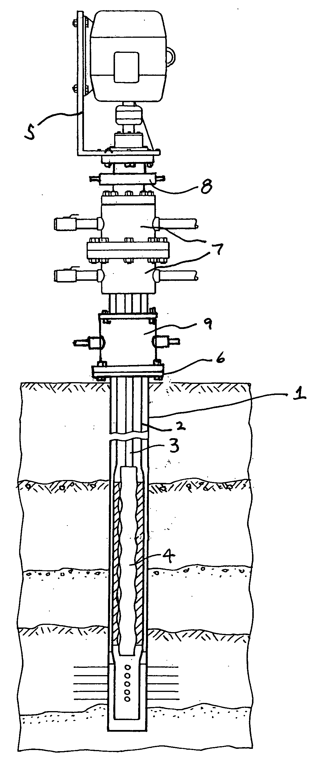
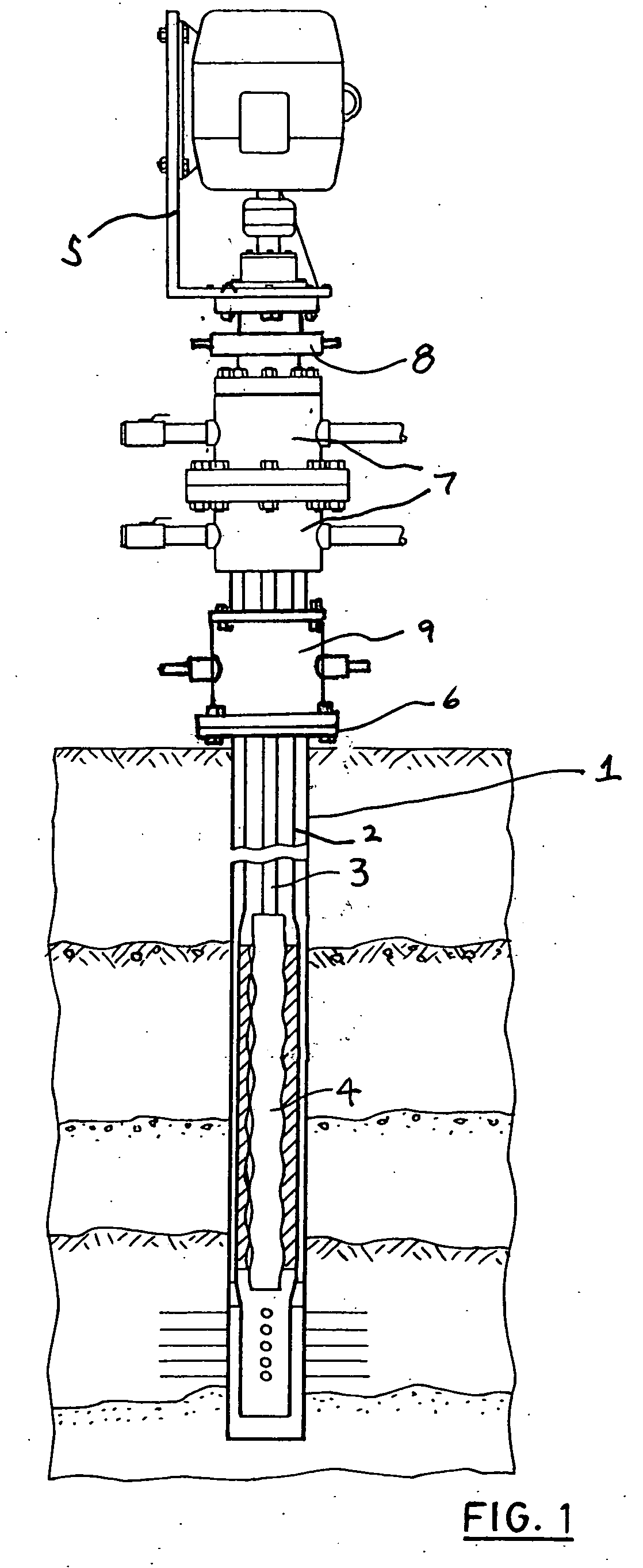
[0029]FIG. 1 is a cross sectional view of a relatively standard oil well. It will be appreciated that depending upon the particular well in question, the set up of the well and the type of equipment used could vary substantially. FIG. 1 depicts but one example of a producing well. In FIG. 1 the well is comprised generally of a casing 1 that extends from the surface of the earth down into an the oil bearing strata. Situated within the casing is a tubing string 2. Within the tubing string there is located a polished rod 3 for driving a downhole pump 4. In the embodiment shown, the pump is a rotary pump with polished rod 3 connected to a rotary drive head 5. Where casing 1 exits the earth ...


PUM


Abstract

A pump rod clamp for gripping a pump rod in an oil, gas or water well. The pump rod clamp comprises a central housing having a longitudinal bore for receiving a pump rod, a plurality of clamping members receivable within the central housing, and one or more actuators to cause the clamping members to be moved between an activated position where they grippingly engage the pump rod and a deactivated position where they are released from contact with the pump rod. Each of the clamping members have a leading face that includes one or more gripping inserts releasably secured thereto. The gripping inserts having outer faces generally aligned with the pump rod for grippingly engaging the pump rod when the clamping members are in their activated position such that force exerted by each individual clamping member against the pump rod is concentrated and distributed over the outer faces of the one or more gripping inserts of each clamping member.

Description

FIELD OF THE INVENTION [0001] This invention relates generally to a pump rod clamp and blowout preventer as may be used on oil, gas water wells, and in particular a new and improved pump rod clamp and blowout preventer having an enhanced polished rod clamping or gripping capability. BACKGROUND OF THE INVENTION [0002] The use of pump rod clamps and blowout preventers on oil, gas and water wells is a common occurrence. Pump rod clamps are used generally to hold the pump or polished rod and may take any one of a wide variety of forms ranging from a pair of rams that are driven radially inward in order to contact the pump rod and hold it in place, to wedges that may be inserted around the rod, to a pair of clamping members that may be bolted around the exterior surface of the rod and hung from a mandrel or other support member. Regardless of the particular structure of the clamp, its primary purpose is to either suspend the rod within the well, and / or to prevent rotational movement of t...

Claims


Application Information

Patent Timeline
Patent Type & Authority Applications(United States)
IPC IPC(8): E21B19/12E21B33/06F16K31/00
CPCE21B33/062E21B19/12
Inventor WRIGHT, ANDREW J.BENTLEY, JAMES
Owner MILLENNIUM OILFLOW SYST & TECH
Learn More