Apparatus and methods for installing instrumentation line in a wellbore

a technology for connecting instruments and wellbores, which is applied in the direction of drilling pipes, wellbore/well accessories, surveying, etc., can solve the problems of affecting the instrumentation line may be subjected to trauma or damage, and the application of such chemicals may be detrimental to the integrity of the instrumentation lin

Active Publication Date: 2005-09-29
WEATHERFORD TECH HLDG LLC
View PDF15 Cites 19 Cited by
  • Summary
  • Abstract
  • Description
  • Claims
  • Application Information

AI Technical Summary

Problems solved by technology

When the instrumentation line is on the outside of a liner or sand screen, the instrumentation line may be subjected to trauma or damage as the liner or sand screen runs into the wellbore.
Further, the instrumentation line may be exposed to the harsh effects of chemicals used in well completion or remediation operations.
For example, it is oftentimes desirable to wash the tubing in order to remove grease and contaminants during a last stage in well completion.
The application of such chemica...

Method used


Image

  • Apparatus and methods for installing instrumentation line in a wellbore
  • Apparatus and methods for installing instrumentation line in a wellbore
  • Apparatus and methods for installing instrumentation line in a wellbore

Examples


Embodiment Construction

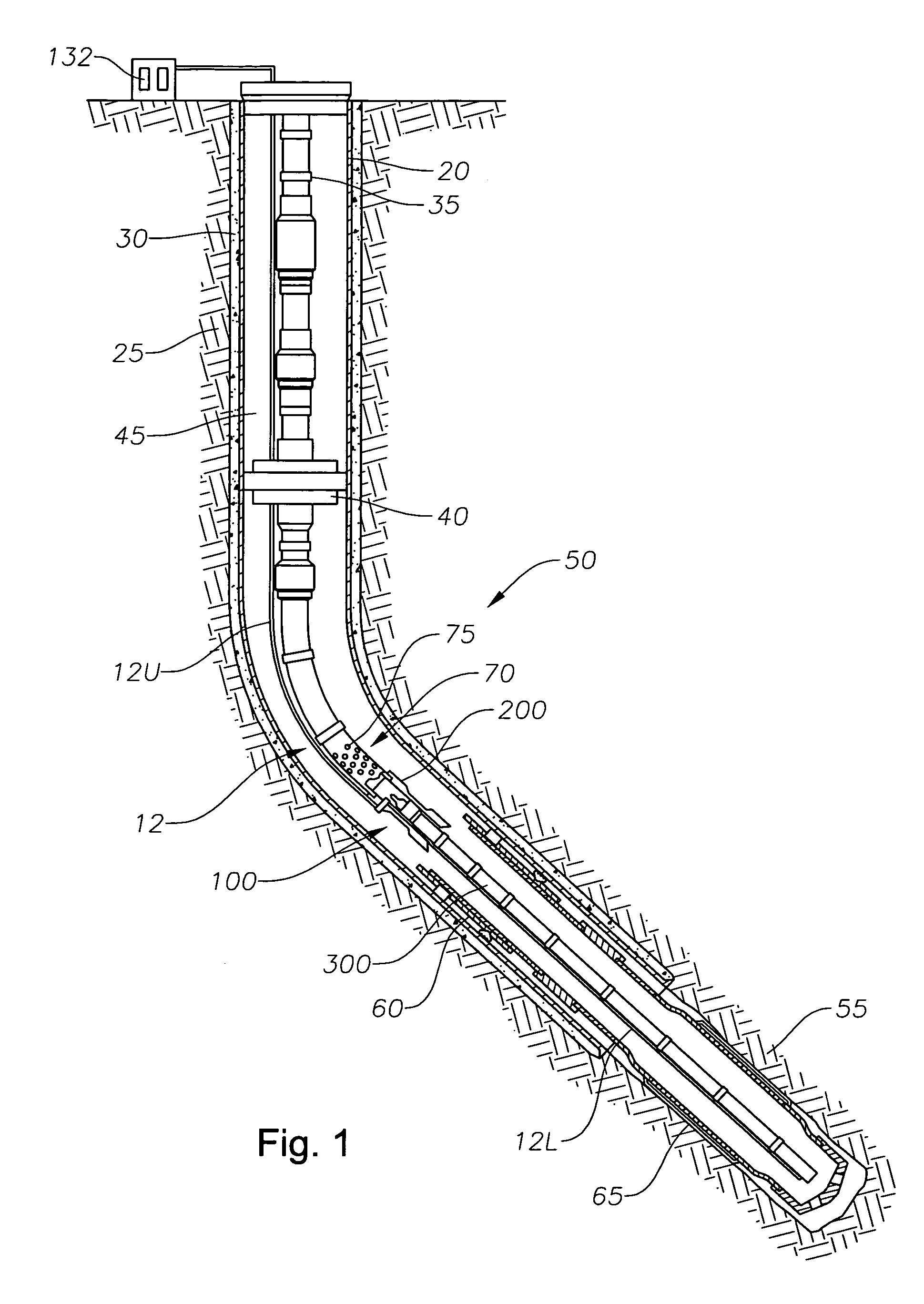
[0025]FIG. 1 illustrates a partial sectional view of an exemplary wellbore 50 that may receive a coupler 100 of the invention. While the coupler 100 is shown generally in FIG. 1, the detail of the coupler 100 will be described in detail with reference to the various figures hereinafter. The wellbore 50 includes a string of casing 20 secured within a surrounding earth formation 25 by cement 30, a tubular string such as production tubing 35 run into the casing 20, an instrumentation line 12 and a packer 40 that seals the annular region 45 between the tubing 35 and the surrounding casing 20. The wellbore 50 is completed with a screen hanger 60 that supports a sand screen 65 adjacent a desired pay zone 55. As shown, the coupler 100 connects to the tubing 35 by a flow sub 70. The flow sub 70 includes perforations 75 that permit the inflow of hydrocarbons for production and the circulation of chemicals around the coupler 100 during later well completion or remediation operations.

[0026] T...


PUM


Abstract

The invention provides a coupler and a method for installing an instrumentation line, such as fiber optic cable, into a wellbore. The coupler places upper and lower instrumentation lines in communication with one another downhole to form a single line. The apparatus comprises a landing tool and a stinger that lands on the landing tool, thereby placing the upper and the lower instrumentation lines in communication. The landing tool is run into the wellbore at the lower end of a tubular, such as production tubing. The upper instrumentation line affixes to the tubing and landing tool and extends to the surface. The lower instrumentation line affixes along the stinger. In this manner, the lower instrumentation line may be installed after expansion of a well screen or liner and may be later removed from the wellbore prior to well workover procedures without pulling the production string.

Description

BACKGROUND OF THE INVENTION [0001] 1. Field of the Invention[0002] The invention generally relates to methods and apparatus for connecting instrumentation lines in a wellbore. More particularly, the invention provides methods and apparatus for delivering a fiber optic cable to a selected depth within a hydrocarbon wellbore. [0003] 2. Description of the Related Art [0004] In a typical oil or gas well, a borehole drilled into the surface of the earth extends downward into a formation to provide a wellbore. The wellbore may include any number of tubular strings such as a string of surface casing cemented into place and a liner string hung off of the casing that extends into a producing zone, or pay zone, where the liner is perforated to permit inflow of hydrocarbons into the bore of the liner. Alternatively, the wellbore may be completed as an open hole which may include a sand screen positioned at the end of the casing to support the formation and filter hydrocarbons that pass thereth...

Claims


Application Information

Patent Timeline
IPC IPC(8): E21B17/02E21B23/03E21B23/14E21B29/00E21B47/00E21B47/01E21B47/12
CPCE21B23/03E21B47/123E21B47/01E21B47/00E21B47/135E21B17/028E21B47/12
Inventor VOLD, GISLEFOSTER, MIKECONSTANTINE, JESSE
Owner WEATHERFORD TECH HLDG LLC
Why Eureka
Try Eureka