Control system for a hybrid electric vehicle to anticipate the need for a mode change

a control system and electric vehicle technology, applied in the direction of electric control, engine starters, instruments, etc., can solve the problems of frequent engine start and stop, limited power capacity, and limited operating range of electric vehicles, so as to improve drivability and efficiency

Inactive Publication Date: 2005-09-29
FORD GLOBAL TECH LLC
View PDF16 Cites 104 Cited by
  • Summary
  • Abstract
  • Description
  • Claims
  • Application Information

AI Technical Summary

Benefits of technology

[0024] Accordingly, an objective of the present invention is to improve the drivability and efficiency of a parallel hybrid electric vehicle (PHEV) powertrain system so that the vehicle has predictable drivability as perceived by the vehicle operator.

Problems solved by technology

However, electric vehicles have limited operating range and limited power capabilities.
They also require substantial time to recharge their batteries.
Frequent engine starts and stops can be annoying, especially if they do not occur in response to any conscious input from the vehicle driver.
Frequent, annoying, high-emission, and engine-wearing “false starts” can occur when the engine is started in response to what later proves to be a very brief demand for power in excess of the motive power threshold but still within the drive capabilities.
This can occur when quickly pulling out into otherwise slow traffic or surging forward in heavy traffic.
Alternatively, starting an engine poses a challenge because its torque is not available instantaneously.
An annoying lag in performance will occur if the engine is not started somewhat in advance of the actual engine torque requirement.
The lack of a startup clutch, as well as the lack of a hydrokinetic torque converter, reduces the inertia mass which permits a faster response to a command force startup torque at the vehicle wheels.
A problem with this prior art system is apparent in an intermediate power range above the power below which it is more efficient to drive with the motor on (perhaps five to ten kW for a typical compact to mid-size vehicle), and below the peak electric-only power capability required for acceptable engine-off launch (twenty to forty kW for the same vehicle).
The control systems of these prior art patents do not describe nor suggest an anticipator function for anticipating the need for a driving state change so that an optimal seamless transition between driving state modes can be achieved.

Method used


Image

  • Control system for a hybrid electric vehicle to anticipate the need for a mode change
  • Control system for a hybrid electric vehicle to anticipate the need for a mode change
  • Control system for a hybrid electric vehicle to anticipate the need for a mode change

Examples


Embodiment Construction

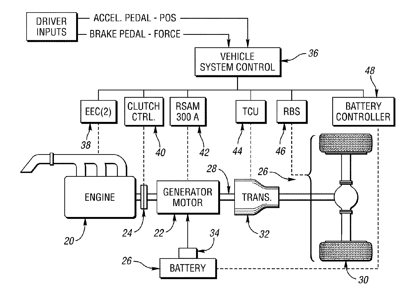
[0040] The invention could be applied to a variety of hybrid electric vehicle powertrain configurations, but two configurations are disclosed as examples. FIG. 1 shows components of a pre-transmission parallel HEV powertrain with an engine disconnect clutch. This pre-transmission configuration is described in co-pending U.S. patent application Ser. No. 10 / 225,824, filed Aug. 22, 2002, now U.S. Pat. No. 6,746,366, which is assigned to the assignee of the present invention.

[0041] An engine 20, shown in FIG. 1, is linked to an electric motor / generator 22 via a disconnect clutch 24. A battery 26 is connected to the motor / generator 22 via an inverter 34, which controls a flow of electrical power to and from the two components. The motor / generator 22, which may be referred to as a drive unit, is connected to a power transfer device 28, such as a drive shaft, which is connected to vehicle traction wheels 30 via a transmission 32. Thus, torque flows from the engine 20 and motor / generator o...


PUM


Abstract

A parallel hybrid electric vehicle method and system including an internal combustion engine (ICE), an electric traction motor/generator, and a controller. A control strategy is provided to prevent unpredicted or undesired engine starts by anticipating the need for the vehicle engine, while avoiding “false starting” the engine or allowing an annoying lag in performance that will occur if the engine is not started in advance of an actual requirement. The invention anticipates the need for engine starts by monitoring vehicle speed and driver demand and their rates of change. The invention allows consistent performance and establishes seamless transitions between engine driving and electromotive driving.

Description

CROSS-REFERENCE TO RELATED APPLICATIONS [0001] This application is a continuation-in-part of U.S. application Ser. No. 10 / 230,707, filed Aug. 29, 2002, which is a continuation-in-part of 09 / 686,472, filed Oct. 11, 2000, now abandoned.BACKGROUND OF THE INVENTION [0002] 1. Field of the Invention [0003] The present invention relates generally to hybrid electric vehicles (HEVs), and specifically to a method and system to improve the efficiency and drivability of a HEV by monitoring vehicle control variables and their rate of change, whereby driver demand is anticipated so that unpredicted or undesired engine false starts and performance lags are prevented. [0004] 2. Background Art [0005] The need to reduce fossil fuel consumption and undesirable engine exhaust gas emissions from vehicles powered by an internal combustion engine (ICE) is well known. Vehicles powered by battery-powered electric traction motors have attempted to address this need. However, electric vehicles have limited op...

Claims


Application Information

Patent Timeline
Patent Type & Authority Applications(United States)
IPC IPC(8): B60K6/48B60W10/06B60W10/08B60W20/00F02N11/08
CPCB60K6/48Y10T477/23B60W10/08B60W20/00B60W2520/10B60W2520/105B60W2540/10B60W2540/12B60W2550/142F02D2041/1411F02N11/0818F02N2200/101F02N2200/102Y02T10/6221Y02T10/6286Y02T10/48B60W10/06B60W2552/15Y02T10/40Y02T10/62B60W2510/244
Inventor TAMOR, MICHAEL
Owner FORD GLOBAL TECH LLC
Why Eureka
Try Eureka