Model based distortion reduction for power amplifiers

a technology of power amplifiers and distortion reduction, applied in amplifiers, amplifier modifications to reduce noise influence, electrical devices, etc., can solve the problems of high-speed, high-quality, and expensive components, and achieve the effect of reducing noise, reducing noise, and reducing distortion

Inactive Publication Date: 2005-09-29
AVAGO TECH WIRELESS IP SINGAPORE PTE
View PDF4 Cites 35 Cited by
  • Summary
  • Abstract
  • Description
  • Claims
  • Application Information

AI Technical Summary

Problems solved by technology

The measurement of the difference between the actual and the desired outputs requires high-quality, high-speed, and therefore, expensive components.

Method used


Image

  • Model based distortion reduction for power amplifiers
  • Model based distortion reduction for power amplifiers
  • Model based distortion reduction for power amplifiers

Examples


Embodiment Construction

[0014] The invention can be implemented in numerous ways, including as a process, an apparatus, a system, a composition of matter, a computer readable medium such as a computer readable storage medium or a computer network wherein program instructions are sent over optical or electronic communication links. In this specification, these implementations, or any other form that the invention may take, may be referred to as techniques. A component such as a processor or a memory described as being configured to perform a task includes both a general component that is temporarily configured to perform the task at a given time or a specific component that is manufactured to perform the task. In general, the order of the steps of disclosed processes may be altered within the scope of the invention.

[0015] A detailed description of one or more embodiments of the invention is provided below along with accompanying figures that illustrate the principles of the invention. The invention is desc...


PUM


Abstract

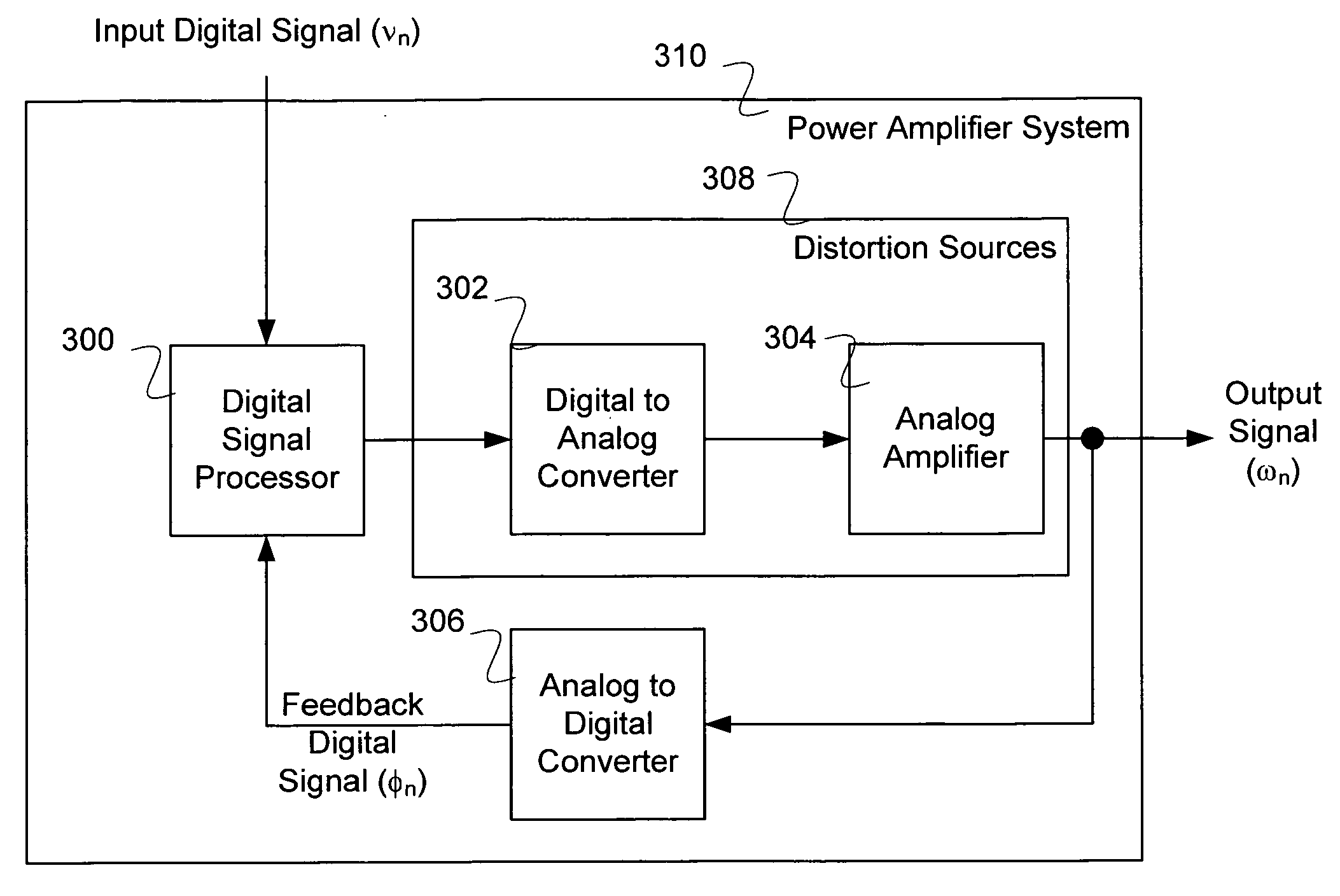
A method of processing a signal is disclosed. The method comprises generating a digital signal, converting the digital signal to an analog signal, and generating an amplified analog signal having distortions. The method further comprises converting the amplified analog signal to a feedback digital signal at a sample rate and updating a model of the distortions based on the feedback digital signal.

Description

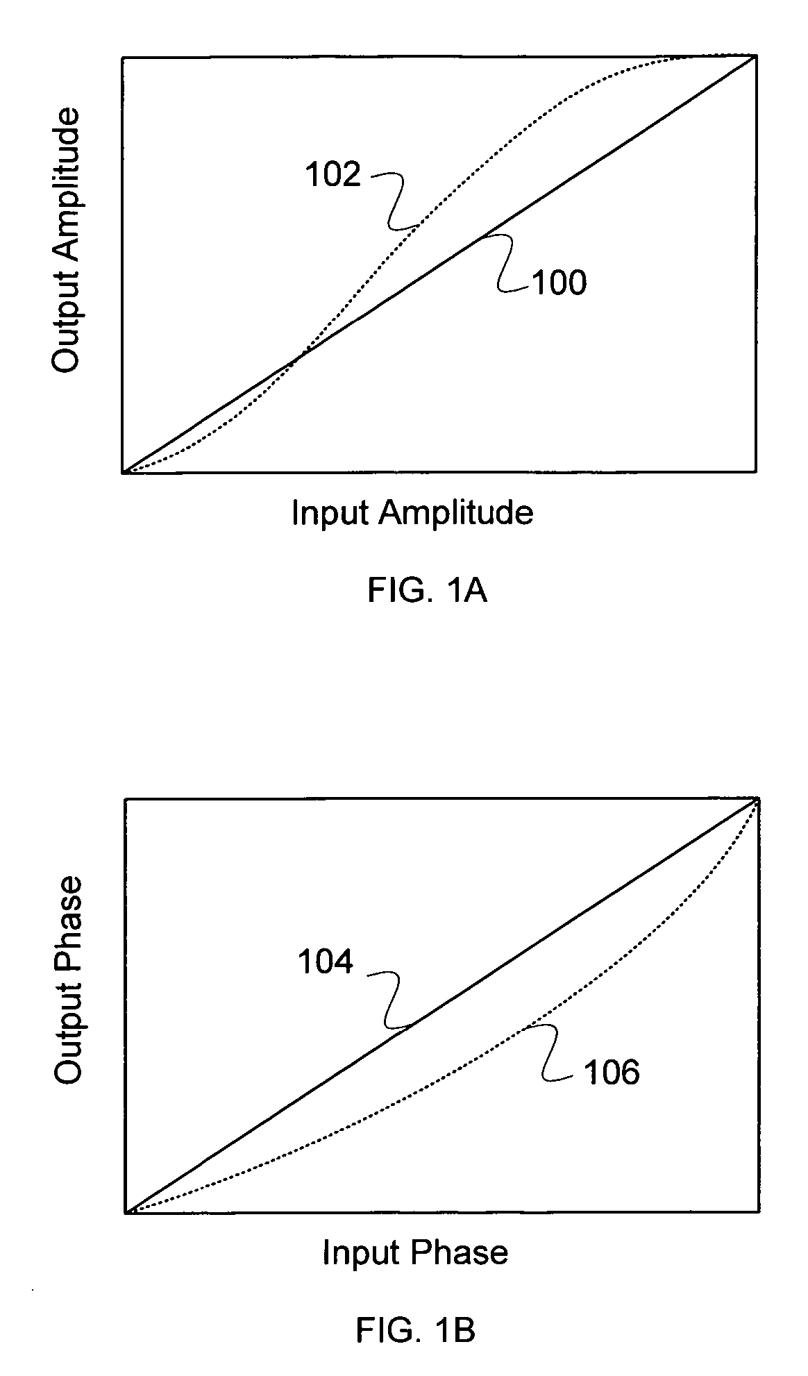
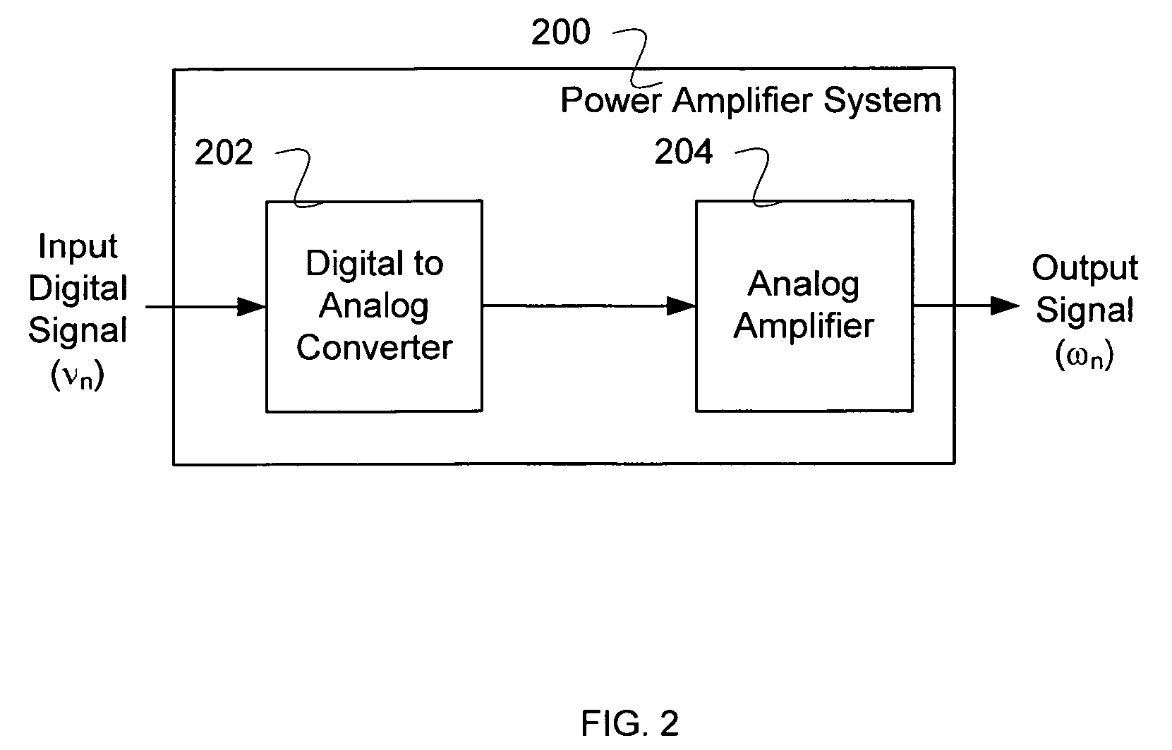
CROSS REFERENCE TO OTHER APPLICATIONS [0001] This application claims priority to U.S. Provisional Patent Application No. 60 / 556,658 (Attorney Docket No. OPTIP009+) entitled POWER AMPLIFIER LINEARIZING SYSTEM filed Mar. 25, 2004, which is incorporated herein by reference for all purposes.BACKGROUND OF THE INVENTION [0002] In designing a power amplifier, a number of factors need to be balanced against each other including specifications like linearity, high efficiency, low cost, or high power. For example, a Doherty-type power amplifier, as described in LUMPED ELEMENT BASED DOHERTY POWER AMPLIFIER TOPOLOGY IN CMOS PROCESS, by Tongchoi et. al. in IEEE Int. Symp. Circuits and Systems, May 2003, pp. 445-448 which is incorporated herein by reference for all purposes, may provide power efficiency at low cost, but may have nonlinearity. Improved linearity can be achieved using active compensation of the amplifier, where a measurement is made of the difference between the actual output of th...

Claims


Application Information

Patent Timeline
Patent Type & Authority Applications(United States)
IPC IPC(8): H03F1/02H03F1/26H03F1/32
CPCH03F1/0288H03F2200/321H03F1/3247H03F1/32H03F1/26
Inventor BATRUNI, ROY G.
Owner AVAGO TECH WIRELESS IP SINGAPORE PTE
Why Eureka
Try Eureka