Control unit and method for reducing interference patterns in the display of an image on a screen

a control unit and image technology, applied in the field of control units and methods for controlling screens, can solve the problems of more complex interference pattern, interference pattern, and generated interference patterns in the display of data, and achieve the effect of avoiding visible interference on the screen

Inactive Publication Date: 2005-09-29
DYNAMIC DATA TECH LLC
View PDF11 Cites 6 Cited by
  • Summary
  • Abstract
  • Description
  • Claims
  • Application Information

AI Technical Summary

Benefits of technology

[0034] It is therefore the object of the present invention to provide a ...

Problems solved by technology

This fact is serious in systems which unite several clock signals (clock domains) on one chip, and which use similar frequencies for digital data processing and analog data acquisition.
It is the problem of such control units that the clock signal couple into one or several inputs of the control chip via the substrate of the control chip 800 and overlay the applied signals.
Thereby, interfering interference patterns are generated in the display of the data on the screen.
Here, merely the base frequencies and not the harmonic frequency portions are considered, which themselves would lead to a diff...

Method used


Image

  • Control unit and method for reducing interference patterns in the display of an image on a screen
  • Control unit and method for reducing interference patterns in the display of an image on a screen
  • Control unit and method for reducing interference patterns in the display of an image on a screen

Examples


first embodiment

[0065] the time-dependent frequency modulation is realized by a time-continuous frequency modulation, such as by the function of a frequency wobbler, which passes a frequency area □f with an appropriate rate, which is fixed by a modulation function g(t) around the base frequency (f0) required by the screen and the memory, respectively.

[0066] Under the assumption that the required clock signals are generated on the control chip by phase locked loops (PLL), the following holds true for the input frequencies fxpllin(t) of the phase locked loops:

fxpllin(t)=f0+□f*g(t)

with: [0067] f0=base frequency of the screen (pixel frequency) or base frequency of the memory [0068]□f=frequency range around the base frequency [0069] g(t)=modulation function

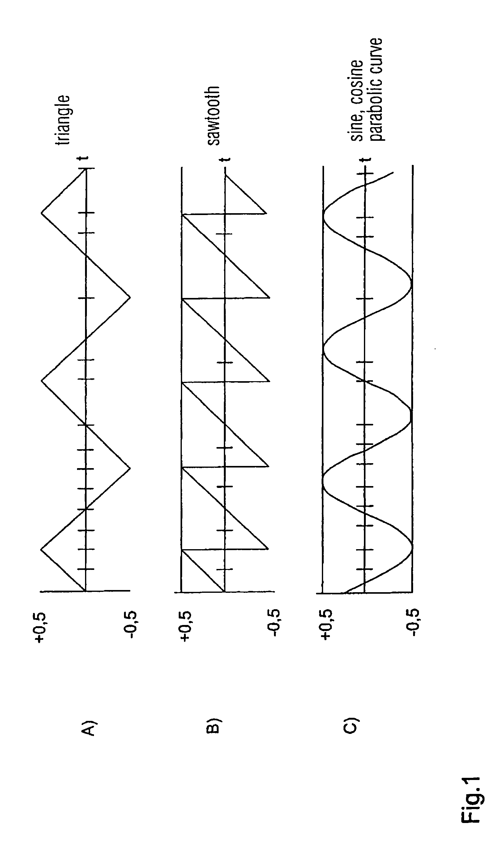
[0070] The modulation function g(t) can be an arbitrary continuous function, such as the functions illustrated in FIG. 1A to 1C, wherein generally no restriction results with regard to the formation and the realization of the used function.

[0071...

second embodiment

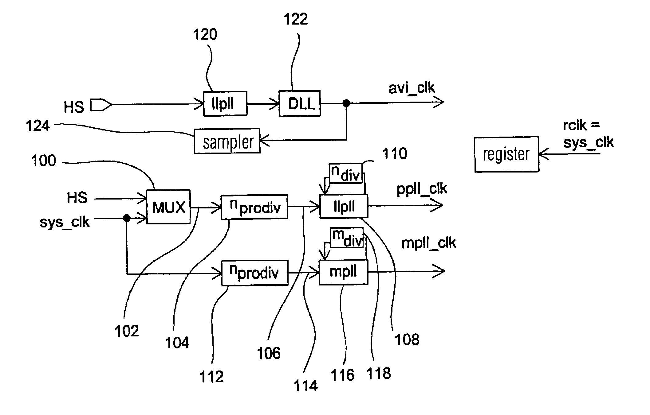
[0096] Thus, according to the present invention for implementing the inventive method, the frequency modulated system clock is generated internally, i.e., in the control unit, namely on the chip. In FIG. 5, a circuit is illustrated for the internal generation of the frequency modulation. As can be seen, the conventionally used external quartz oscillator 126, which is disposed on the circuit board, is maintained to provide the system clock sys_clk to the control chip. Additionally to the already above-described elements, a divider controller 132 is provided, which is connected to the first pre-divider 104 via a first control bus 134, to the second pre-divider 112 via a second control bus 136, to the first feedback divider 110 via a third control bus 138 and to the second feedback divider 118 via a fourth control bus 140.

[0097] The realization illustrated in FIG. 5 is an implementation of the decorrelation by an “on chip” frequency modulation, which is more elegant and technically muc...


PUM


Abstract

A control unit and a method are provided to reduce an interference pattern in the display of an image on a screen with a pixel frequency. The image is described by pixel data and provided to the screen by a control unit. During the generation of pixel data, the clock signals used in the generation of the pixel data are varied or the pixel frequency is changed.

Description

CROSS-REFERENCE TO RELATED APPLICATION [0001] This application is a continuation of and claims priority to co-pending International Application No. PCT / EP03 / 09633, filed Aug. 29, 2003, which designated the United States, which claimed priority to German Patent Application No. 102 41 343.6, filed on Sep. 6, 2002, and which is incorporated herein by reference in its entirety.BACKGROUND OF THE INVENTION [0002] 1. Field of the Invention [0003] The present invention relates to a control unit and a method for controlling a screen, and here particularly to a control unit and a method for reducing interference patterns in a display of an image on the screen. Particularly, the present invention relates to a method and a control unit for usage with a TFT / LCD screen. [0004] 2. Description of the Related Art [0005] Complex systems, which use a plurality of signal, show increasing interactions between digital and analog components with increasing decrease of pattern size. This fact is serious in...

Claims


Application Information

Patent Timeline
IPC IPC(8): G09G5/00
CPCG09G3/2092G09G3/3648H03L7/197G09G2310/08G09G2330/06G09G5/18
Inventor ENGELHARDT, OLIVERECKHARDT, ANDREAS
Owner DYNAMIC DATA TECH LLC
Why Eureka
Try Eureka