Photoelectric sensor

a technology of photoelectric sensor and surface, applied in the field of photoelectric sensor, can solve the problem that the color of light that produces the largest difference between the reflected quantity of light from the mark and the surface of the object is not always the most suitable color, and achieve the effect of accurately and stably detecting the mark on the surface of the obj

Inactive Publication Date: 2005-09-29
PANASONIC INDAL DEVICES SUNX
View PDF3 Cites 2 Cited by
  • Summary
  • Abstract
  • Description
  • Claims
  • Application Information

AI Technical Summary

Benefits of technology

[0008] Therefore, an object of the present invention is to provide a photoelec...

Problems solved by technology

Accordingly, the color of light that produces the largest difference between the reflected quantities of li...

Method used


Image

  • Photoelectric sensor
  • Photoelectric sensor
  • Photoelectric sensor

Examples


Embodiment Construction

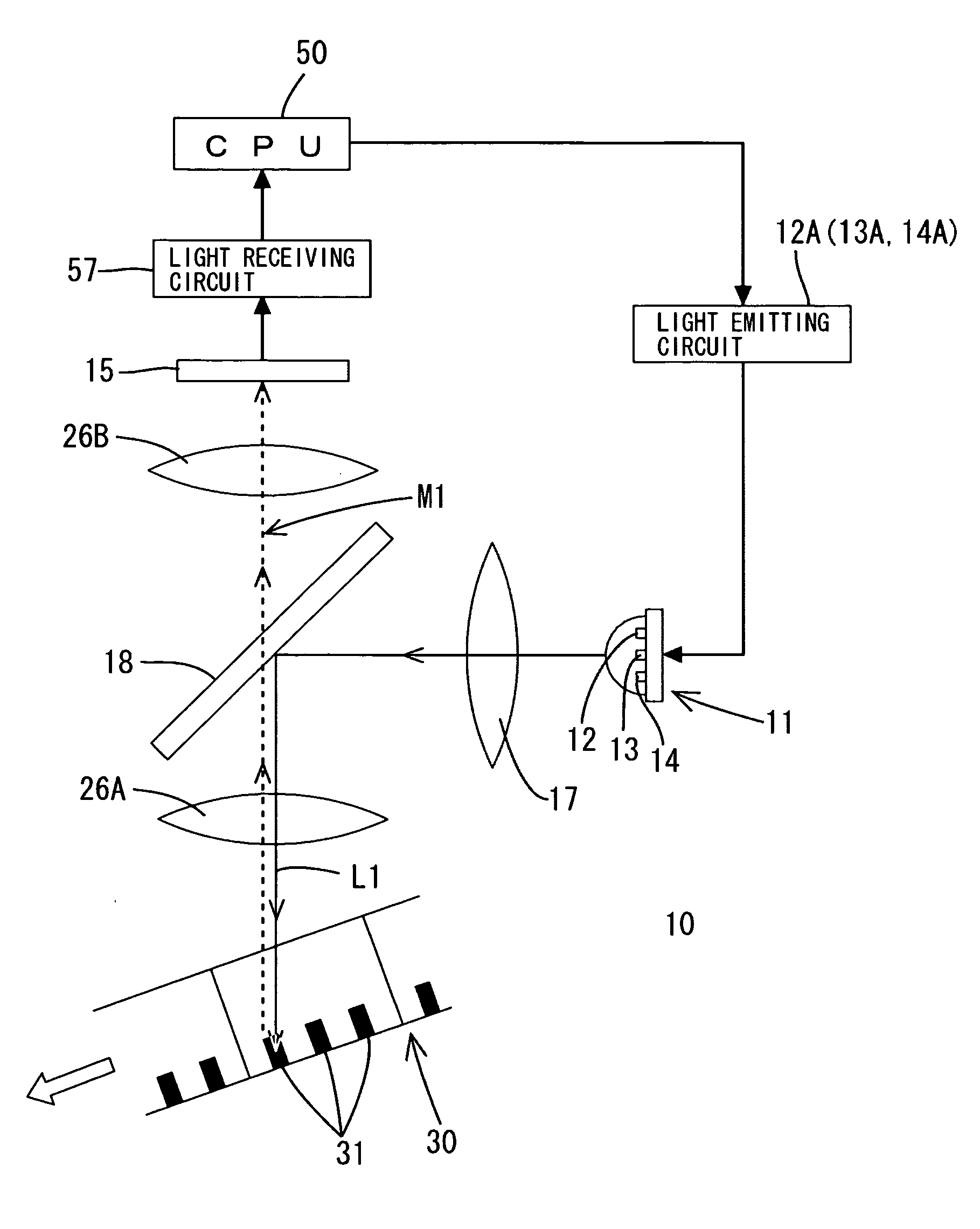
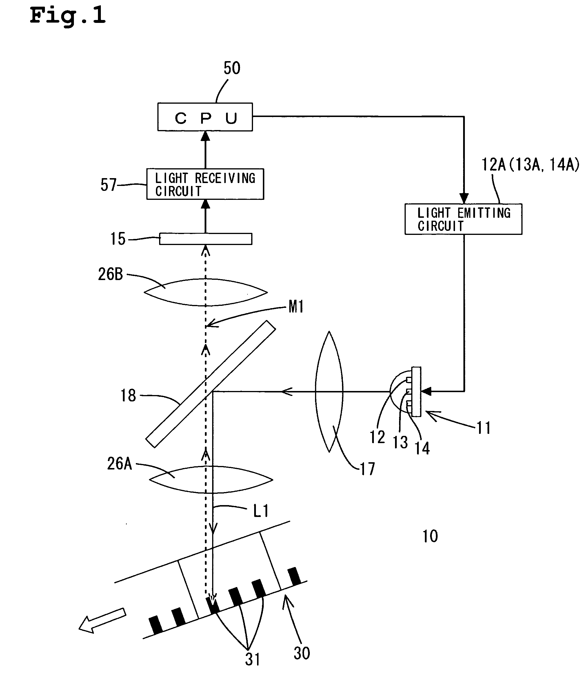
[0034] One embodiment of the present invention will be described with reference to the accompanying drawings. Referring to FIG. 1, the photoelectric sensor 10 is shown as an embodiment of the invention. For example, the photoelectric sensor 10 may be used to detect a mark 31 on a sheet 30 (an object) conveyed by rollers (not shown). The photoelectric sensor 10 comprises a light-emitting element 11 (light-emitting device) emitting a light that shines (i.e., is irradiated or illuminated) onto the sheet 30 (the surface) and a light-receiving element 15 (light-receiving device) receiving light reflected from the sheet 30. The light-receiving element 15 generates a signal according to the quantity level of received light. The mark 31 is detected on the basis of the received light quantity level. In detection of the mark 31, an operating mode is adapted to be switched by an operator between a mark detecting mode and a color detecting mode. Consequently, two different types of detecting op...


PUM


Abstract

A photoelectric sensor includes a light-emitting element and a light-receiving element and detects a mark on an object. Prior to the detection of the mark, a reference received light quantity level is sampled for the surface of an object not including the mark, for every color of light. A mark received light quantity level is then sampled for every color of light. The difference is obtained between the reference received light quantity level and the corresponding mark received light quantity level for each color of light. A ratio of the obtained difference to the reference received light quantity level is obtained. For the colors of light where the difference equals or exceeds a predetermined value, the color of light having the largest ratio is selected for emission from the light-emitting element in the detection of the mark.

Description

BACKGROUND OF THE INVENTION [0001] 1. Field of the Invention [0002] This invention relates to a photoelectric sensor. [0003] 2. Description of the Related Art [0004] Photoelectric sensors have been conventionally known. A conventional photoelectric sensor involves a mark affixed to a surface of an object. The mark typically has a different color than the surface of the object. The object is conveyed through a detection field and a visible light is emitted from light-emitting device so as to shine (i.e., irradiate, illuminate) onto the mark and the object's surface as they pass through the detection field. A light-receiving device ascertains the reflected light from the mark and the object. The photoelectric sensor is able to detect the mark on the object based upon a quantity of light received. The quantity of light reflected and received varies according to the differences in the color of the mark and the color of the surface of the object. Accordingly, the mark on the object is de...

Claims


Application Information

Patent Timeline
IPC IPC(8): G01J3/46G01J3/50G06K7/10G06K7/12H01L31/12
CPCG01J3/0264G01J3/0291G01J3/50G06K7/12G01J2003/466G06K7/10584G01J3/501
Inventor OCHIAI, TAKAYUKI
Owner PANASONIC INDAL DEVICES SUNX
Why Eureka
Try Eureka