
Network device provided with ethernet interface

a network device and interface technology, applied in the field of network devices provided with ethernet interfaces, can solve the problems of incomplete interconnection between devices, inability to set (turn on) auto negotiation, and inability to connect completely, so as to eliminate the problem of incomplete interconnection of devices

Inactive Publication Date: 2005-09-29
FUJITSU LTD
View PDF5 Cites 15 Cited by
  • Summary
  • Abstract
  • Description
  • Claims
  • Application Information

AI Technical Summary

Benefits of technology

[0017] An object of the present invention is to provide a network device provided with an Ethernet interface able to eliminate the problem of incomplete interconnectivity of devices.
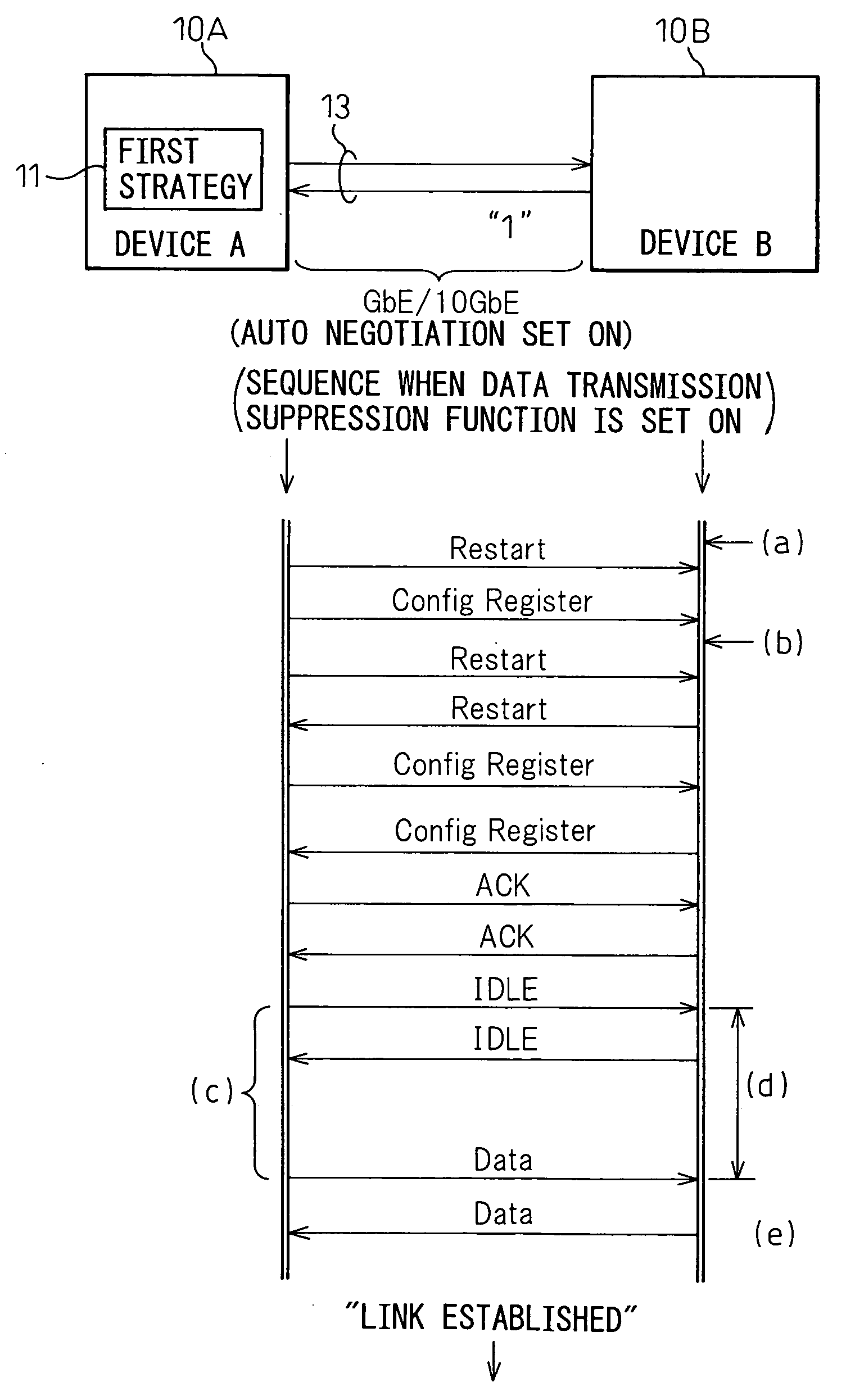
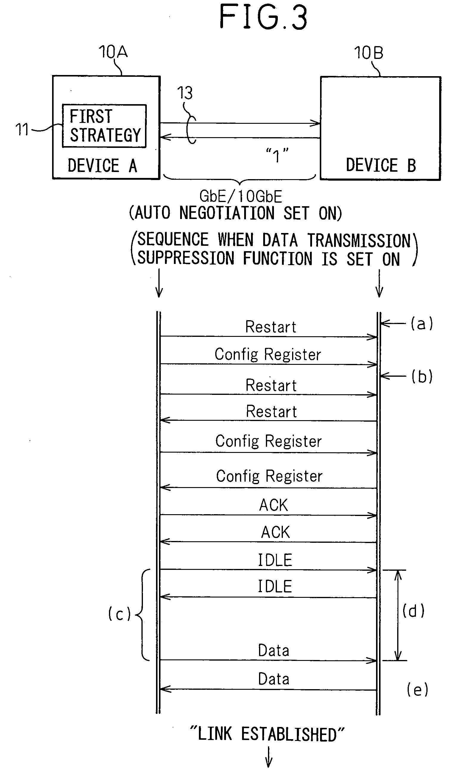
[0018] To attain the above object, the present invention provides a network device (10A) provided with an Ethernet interface for interconnecting with another network device (10B) by auto negotiation, the device comprising a link establishing means (11) for compulsorily establishing a link with the other device (10B) and an on / off setting means (12) for setting the function of the link establishing means (11) on or off. The link establishing means (11) is preferably comprised of a data transmission suppressing unit (21) for suppressing the transmission of user data to the other device (10B) until the sequence based on the auto negotiation is finished. This solves the problem of connectivity where a link cannot be established even with repeated sequences of auto negotiation.

Problems solved by technology

The above auto negotiation function supported by the network devices (Ethernet devices) has the problem that the interconnectivity is not perfect, that is, there is a problem in connectivity between devices.
This is due to the vagueness of the provisions of IEEE 802.3 and has resulted in the various manufacturers supplying physical layer chips (PHY chips) with different specifications and consequently the incompleteness of connectivity when setting (turning on) auto negotiation.

Method used


Image

  • Network device provided with ethernet interface
  • Network device provided with ethernet interface
  • Network device provided with ethernet interface

Examples


Embodiment Construction

[0035] Preferred embodiments of the present invention will be described in detail below while referring to the attached figures.

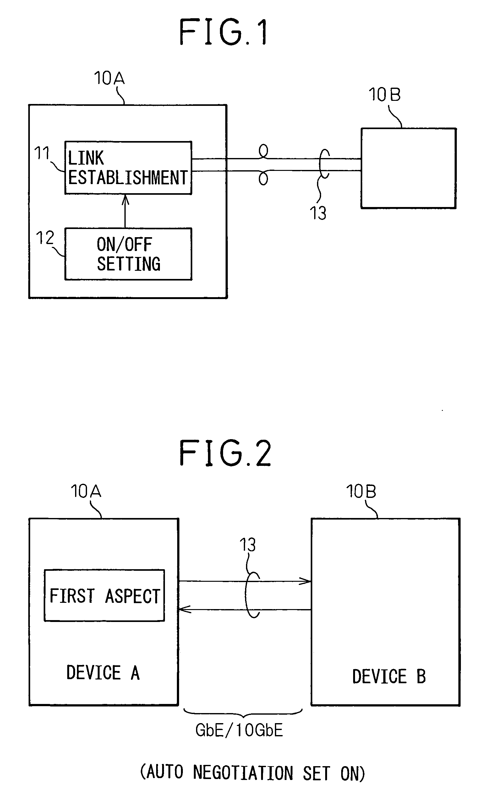
[0036]FIG. 1 is a view of the basic configuration of the present invention. In the figure, reference numeral 10A shows the network device in question. The device to be communicated with is indicated by reference numeral 10B.

[0037] This network device 10A is a network device provided with an Ethernet interface and interconnecting with the device 10B by auto negotiation. The point characterizing this device 10A is the provision of the illustrated link establishing means 11 and the on / off setting means 12. Specifically, these are the link establishing means 11 for compulsorily establishing a link 13 with the other device 10B and the on / off setting means 12 for setting on / off the function of the link establishing means 11.

[0038] By setting the on / off setting means 12 on, the link establishing means 11 built into the network device 10A operates, whereby the a...


PUM


Abstract

A network device provided with an Ethernet interface for interconnecting with another network device by auto negotiation, the network device comprising a link establishing function unit compulsorily establishing a link with the other network device and an on / off setting function unit setting the function of the link establishing function unit on or off and the link establishing function unit being comprised of a data transmission suppressing unit for suppressing the transmission of user data to the other network device until the sequence based on the auto negotiation is finished, whereby the problem of connectivity where the sequence of the auto negotiation repeats and no link can be established is solved.

Description

BACKGROUND OF THE INVENTION [0001] 1. Field of the Invention [0002] The present invention relates to a layer 2 / layer 3 switch, transmission device, or other network device provided with an Ethernet (registered trademark, same below) interface (Ethernet device), more particularly relates to a network device designed to improve the operation of an auto negotiation function supported by that device used in a layer 2 / layer 3 network over which carriers are primarily launching new services. Note that the auto negotiation function is a function for automatic selection of a communication mode among network devices and is defined by IEEE 802.3. [0003] 2. Description of the Related Art [0004] Along with the faster speeds and broader bands of data communications in recent years, demand for services by inexpensive Ethernet interfaces able to accommodate user interfaces as well has been soaring. [0005] At the present time, connection of Ethernet interfaces used by carriers requires use of the a...

Claims


Application Information

Patent Timeline
IPC IPC(8): H04L12/28H04J1/16H04J3/14H04L1/00H04L12/26H04L12/413H04L12/46H04L12/66H04L29/08H04L29/10
CPCH04L12/40136H04L12/46
Inventor KONUMA, YOICHISAIKI, KOICHIFUKAGAWA, TAKASHIKAWARAI, MASASHIGE
Owner FUJITSU LTD
Learn More