Fluid machine

Inactive Publication Date: 2005-09-29
NIPPON SOKEN +1
View PDF13 Cites 83 Cited by
  • Summary
  • Abstract
  • Description
  • Claims
  • Application Information

AI Technical Summary

Benefits of technology

[0012] It is, therefore, an object of the present invention, in view of the above mentioned problems, to provide a fluid machine which increases a sealing effect of scroll wraps, in

Problems solved by technology

When the scroll type compression device is used as the expansion device, there is a problem in that the fluid machine can not perform the expansion operation at its maximum efficiency.
When the working chamber reaches at its end stroke (comes to its outermost working chamber position), the pressure of the working fluid has still a certain high amount and therefore is likely to

Method used


Image

  • Fluid machine
  • Fluid machine
  • Fluid machine

Examples


first embodiment

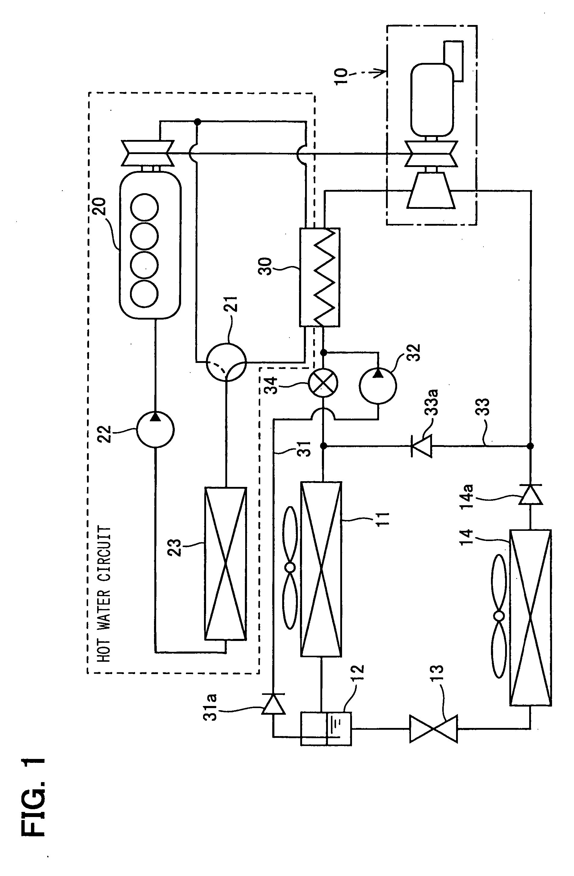
[0032] A first embodiment of the present invention will now be explained with reference to FIG. 1. A fluid machine 10 of the present invention is used to, for example, a gas compression type refrigerating machine for a Rankine cycle for a motor vehicle. The gas compression type refrigerating machine for the Rankine cycle collects energy from waste heat generated by an internal combustion engine 20, which generates a driving force for the motor vehicle. In addition, in the fluid machine 10 of the present invention, the heat generated by the fluid machine is utilized for performing an air-conditioning operation for the motor vehicle.

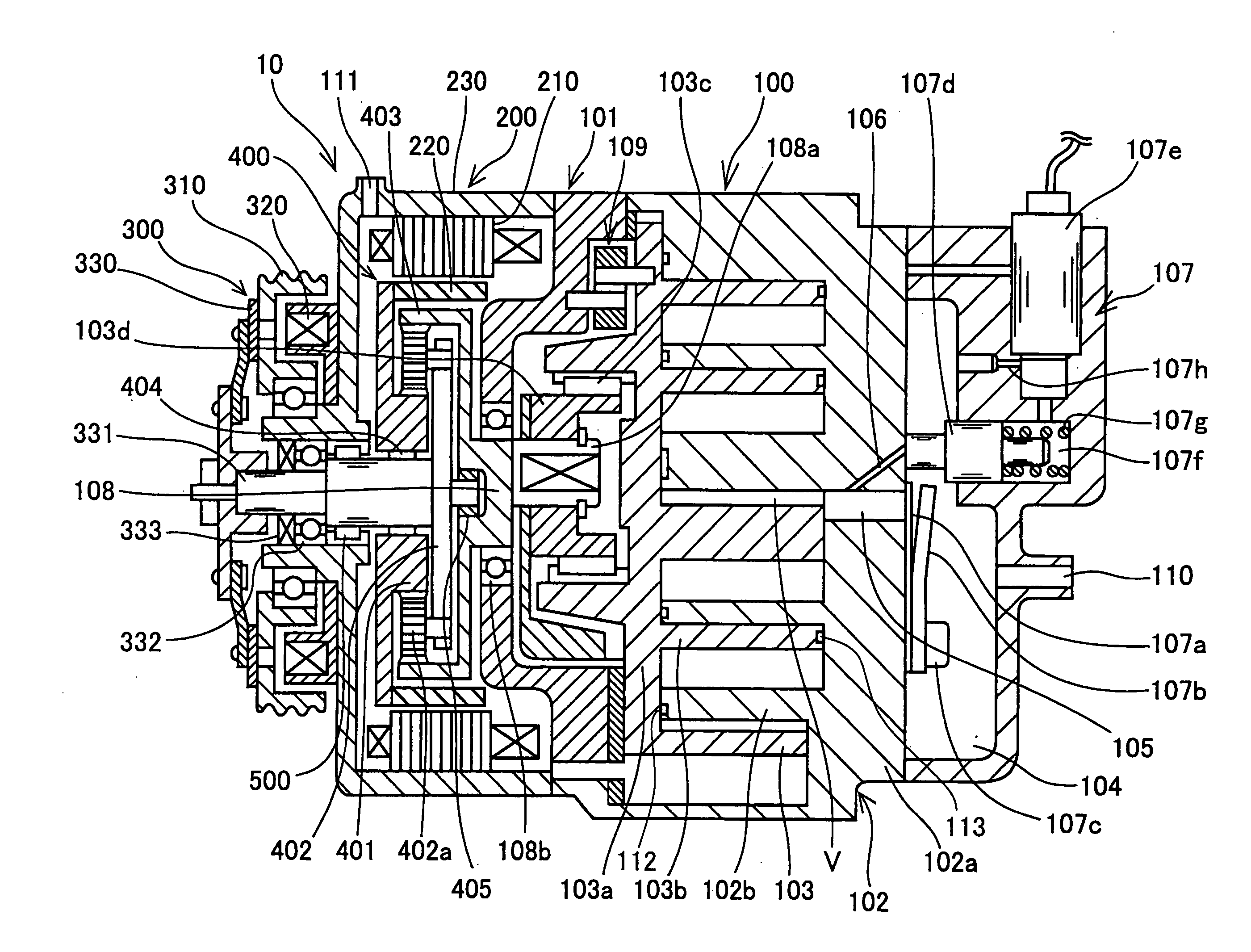
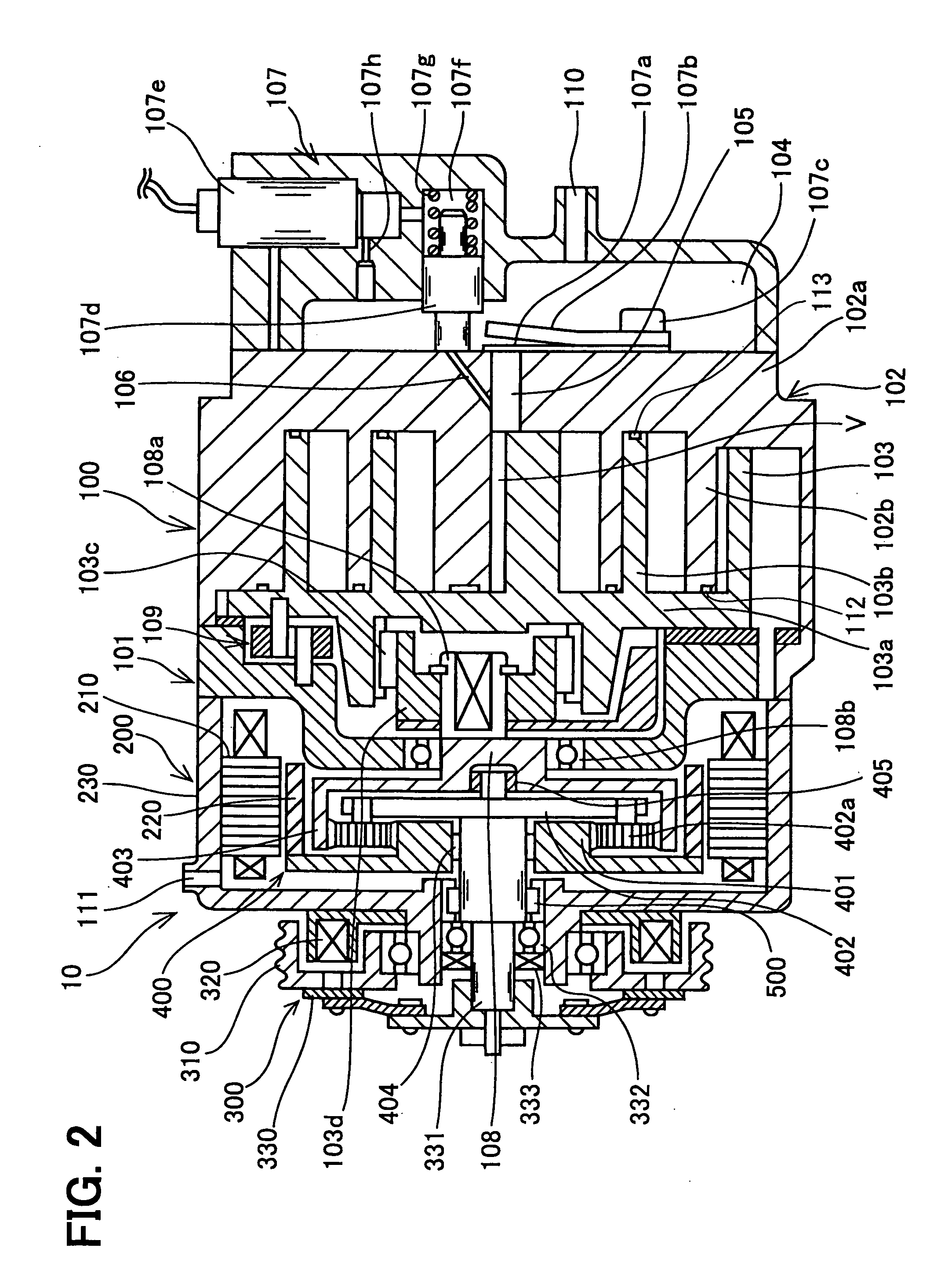
[0033] In FIG. 1, a reference numeral 10 designates the fluid machine comprising an expansion-and-compressor device, so that the fluid machine operates as a compressor for compressing a gas-phase refrigerant (this is referred to as a pump mode operation) and also as a power generator for generating a mechanical driving force by converting fluid pressure o...

second embodiment

[0101]FIGS. 9A to 9C show the movable scroll 103 according to a second embodiment, wherein FIG. 9A is a top plan view when viewed from the electric rotating device 200, FIG. 9B is a cross sectional view, and FIG. 9C is a top plan view when viewed from the fixed scroll 102.

[0102] As already explained, according to the first embodiment shown in FIG. 4C, the back side of the scroll wrap 103b is partly formed with the thin flanged portion H, because the diameter “D2” of the thick portion is made smaller than the diameter “D1” of the thick portion of the conventional movable scroll shown in FIG. 5A.

[0103] According to the second embodiment, a hatched area “I” of the movable scroll 103 is formed with the thick portion, as shown in FIG. 9A, so that all area of the back side of the scroll wrap 103b is formed with the thick portion, and only such a portion of the back side, at a front side of which the scroll wrap 103b is not formed, is formed with the thin flanged portion H.

[0104] With s...

third embodiment

[0105]FIGS. 10A to 10C show the movable scroll 103 according to a third embodiment, wherein FIG. 10A is a top plan view when viewed from the electric rotating device 200, FIG. 10B is a cross sectional view, and FIG. 10C is a top plan view when viewed from the fixed scroll 102.

[0106] According to the third embodiment, the thick portion of the base plate 103a is made to be identical to that of conventional movable scroll, so that the diameter of the thick portion 103a is made to be “D1”, as shown in FIG. 10A. And a flanged thin portion (an outwardly extended portion) “T” is formed at an outer periphery of the base plate 103a. An outer shape of the movable scroll 103 of third embodiment is identical to the first and second embodiment, so that the chip seal 112 is always kept in the sliding contact with the bottom surface of the movable scroll 103. Accordingly, the same sealing effect to the first and second embodiments can be obtained in the third embodiment.


PUM


Abstract

An outer end of a seal element for a fixed scroll is extended to a position close to an end of an inside spiral wall of the fixed scroll, and an outwardly extended portion is formed at an outer periphery of a disc-shaped base plate of a movable scroll, so that a bottom surface of the movable scroll is always kept in a sliding contact entirely with the seal element during the orbital movement of the movable scroll. A thickness of the outwardly extended portion formed at the outer periphery of the disc-shaped base plate is made smaller than that of the disc-shaped base plate, so that the weight of the fluid machine can be smaller.

Description

CROSS REFERENCE TO RELATED APPLICATION [0001] This application is based on Japanese Patent Application Nos. 2004-87740 filed on Mar. 24, 2004 and 2005-4449 filed on Jan. 11, 2005, the disclosures of which are incorporated herein by reference. FIELD OF THE INVENTION [0002] The present invention relates to a fluid machine for converting energy of working fluid into mechanical rotational force. The fluid machine according to the present invention is an expansion and compression device to be used in a Rankine cycle for collecting heat energy, wherein the fluid machine has a pump mode operation for compressing and discharging the working fluid, and a motor mode operation for converting fluid pressure into kinetic energy to obtain the mechanical rotational force. BACKGROUND OF THE INVENTION [0003] In a prior art fluid machine, for example shown in Japanese (Non-examined) Patent Publication S63-96449, heat energy is collected by Rankine cycle, wherein a compressor is also used as an expans...

Claims


Application Information

Patent Timeline
IPC IPC(8): F01C1/02F01C1/063F01C19/08F01D1/38F01D15/00F03C2/00F03C4/00F04C2/00F04C18/00F04C18/02F25B1/04F25B31/00
CPCF25B1/04F01C1/0246
Inventor OGAWA, HIROSHIHOTTA, TADASHIIWANAMI, SHIGEKIUNO, KEIICHI
Owner NIPPON SOKEN
Why Eureka
Try Eureka