Green-state ceramic discharge vessel parts

a discharge vessel and ceramic technology, applied in the field of ceramic discharge vessels, can solve the problems of misalignment of capillaries, unsuitable for assembling such discharge vessels,

Inactive Publication Date: 2005-09-29
OSRAM SYLVANIA INC
View PDF14 Cites 9 Cited by
  • Summary
  • Abstract
  • Description
  • Claims
  • Application Information

AI Technical Summary

Benefits of technology

[0007] An object of the present invention is to provide a novel structure for a green-state discharge vess

Problems solved by technology

However, some discharge vessels parts do not have capillaries on opposite sides of a body and thus the device in FIG. 1 would not be suitable for assembling such discharge vessels.
The par

Method used


Image

  • Green-state ceramic discharge vessel parts
  • Green-state ceramic discharge vessel parts
  • Green-state ceramic discharge vessel parts

Examples


Embodiment Construction

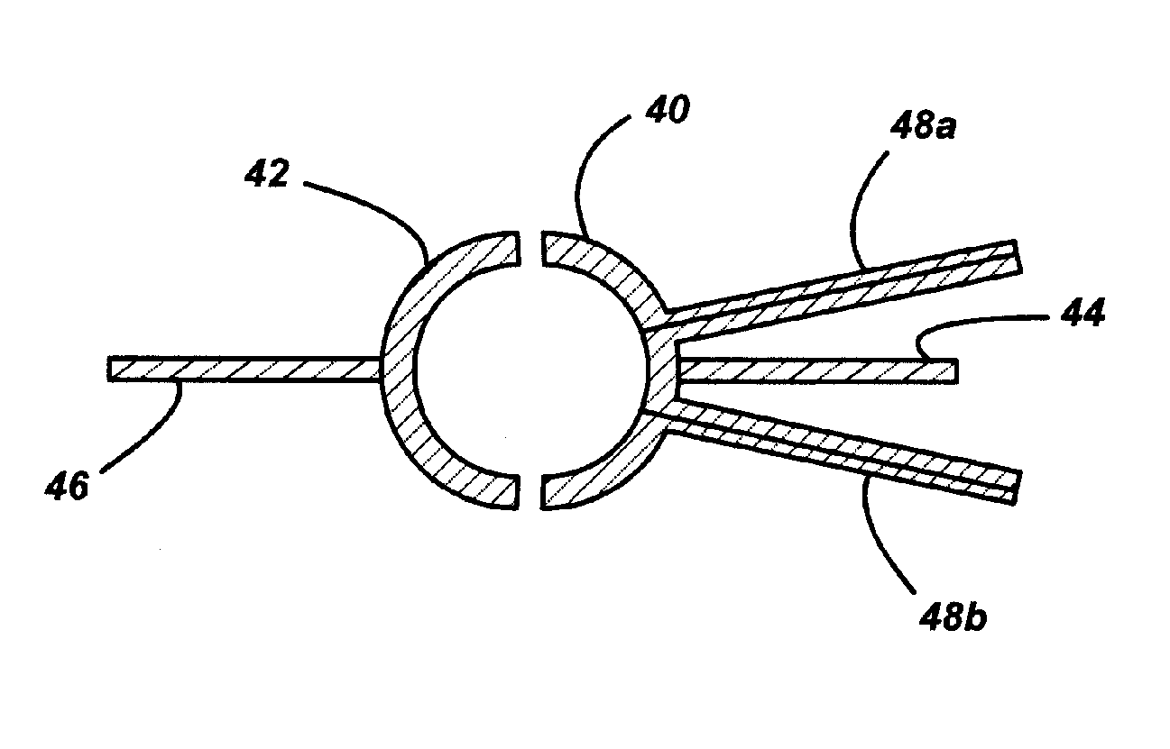
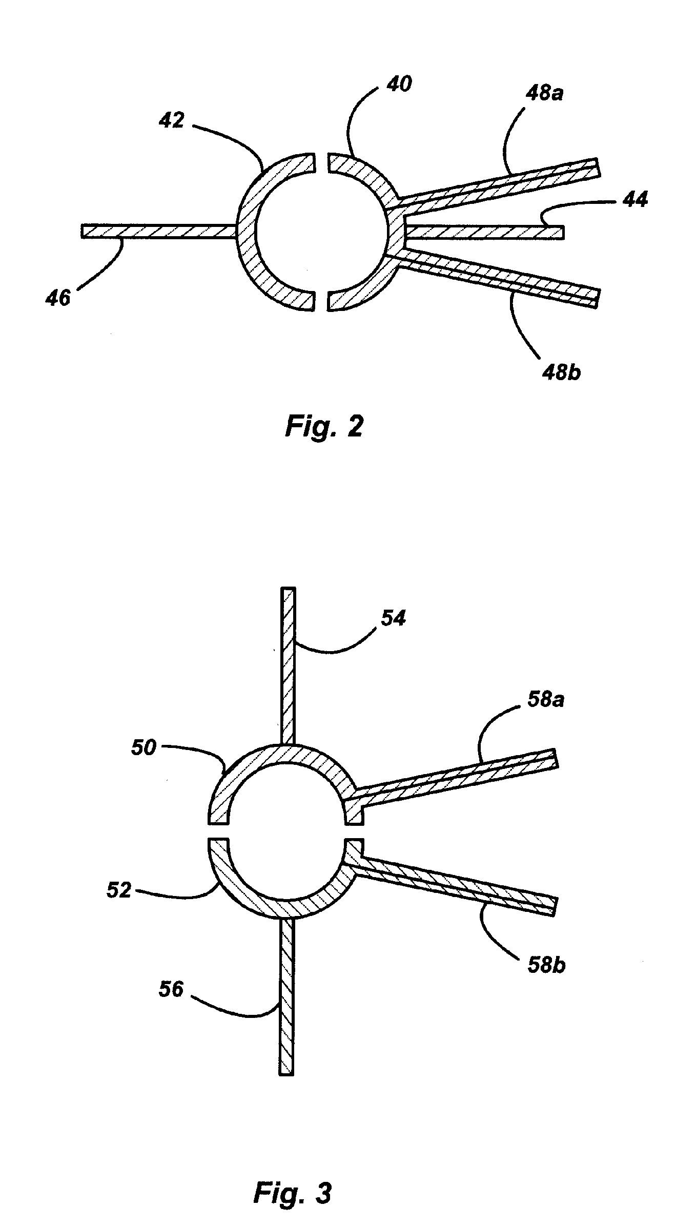
[0013] With reference now to FIGS. 2 and 3, a ceramic discharge vessel in a green state prior to assembly includes a first discharge vessel part 40, 50 in a green state, a second discharge vessel part 42, 52 in a green state, where the first and second discharge vessel parts are adapted to form a discharge vessel when joined together, and, to facilitate joining together the first and second discharge vessel parts, a first removable handle 44, 54 temporarily attached to the first discharge vessel part 40, 50 for maneuvering the first discharge vessel part and a second removable handle 46, 56 temporarily attached to the second discharge vessel part 42, 52 for maneuvering the second discharge vessel part. The first and second removable handles are used to position the first and second discharge vessel parts in a device that joins the two parts together to form a discharge vessel, such as the device shown in FIG. 1 or other similar devices.

[0014] The removable handles are removed at a ...


PUM


Abstract

A ceramic discharge vessel in a green state prior to assembly includes a first discharge vessel part in a green state, a second discharge vessel part in a green state, wherein the first and second discharge vessel parts form a discharge vessel when joined together, and a first capillary attached to the first discharge vessel part and a second capillary attached to one of the first and second discharge vessel parts. To facilitate joining the first and second discharge vessel parts, a first removable handle is temporarily attached to the first discharge vessel part for maneuvering the first discharge vessel part, and a second removable handle is temporarily attached to the second discharge vessel part for maneuvering the second discharge vessel part.

Description

BACKGROUND OF THE INVENTION [0001] The present invention is directed to a ceramic discharge vessel for a high intensity discharge lamp and more particularly to the structure of parts of the discharge vessel that are in a green state during assembly of the discharge vessel. [0002] Commercial ceramic discharge vessels typically include a polycrystalline alumina (PCA) ceramic. Alumina powder is mixed with a binder and the mixture is formed into a desired shape by isostatic pressing, extrusion or injection molding. The binders help a molded alumina part retain its shape while the part is in its “green state” (prior to binder removal and sintering). [0003] U.S. Pat. No. 6,620,272, which is incorporated by reference, describes a method for assembling a ceramic body in which two ceramic halves of a discharge vessel are joined together. The surfaces to be joined are heated to cause localized melting and then brought together and joined at a seam by alternately compressing and stretching the...

Claims


Application Information

Patent Timeline
IPC IPC(8): H01J9/00H01J9/26H01J61/30H05B33/10
CPCH01J61/30H01J9/266
Inventor NEIL, JEFFREY T.ZASLAVSKY, GREGORYPEREZ, VICTOR E.LIMA, JOSEPH V.
Owner OSRAM SYLVANIA INC
Why Eureka
Try Eureka