Reamer spindle for minimally invasive joint surgery

a technology of acetabular reamer and handle, which is applied in the field of adjustable handles for acetabular reamers, can solve the problems of affecting the operation efficiency of the reamer, the device that is not properly cleaned and sterilized contributes to the risk of disease transmission from patient to patient, etc., to achieve the effect of maximum control in different orientations, enhanced comfort for holding and using the instrument, and easy cleaning

Active Publication Date: 2005-09-29
VIANT AS&O HLDG LLC
View PDF9 Cites 50 Cited by
  • Summary
  • Abstract
  • Description
  • Claims
  • Application Information

AI Technical Summary

Benefits of technology

[0006] An adjustable reamer spindle is provided to aid the surgeon in controlling the instrument. Adjustment of the position of the handle axis of the spindle enables the axis through the palm/grip of each hand to change in order to provide maximum control in different orientations. The adjustment is desirable in order to accommodate operating on the left or right side of the patient, standing behind or in-front of the patient, or the use of a different surgical approach. Further, adjustment is important to accommodate the differing needs of surgeons who are naturally left or right handed. Thus, the comfort for holding and using the instrument is...

Problems solved by technology

Complicated mechanical devices have crevasses and recesses that are difficult, if not almost impossible, to clean with ease.
Devices that are not properly cleaned and sterilized contribute to the risk of disease transfer from patient to patient following the emergence of certain “prions” that are not killed by norma...

Method used


Image

  • Reamer spindle for minimally invasive joint surgery
  • Reamer spindle for minimally invasive joint surgery
  • Reamer spindle for minimally invasive joint surgery

Examples


Embodiment Construction

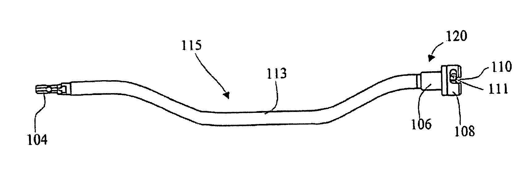
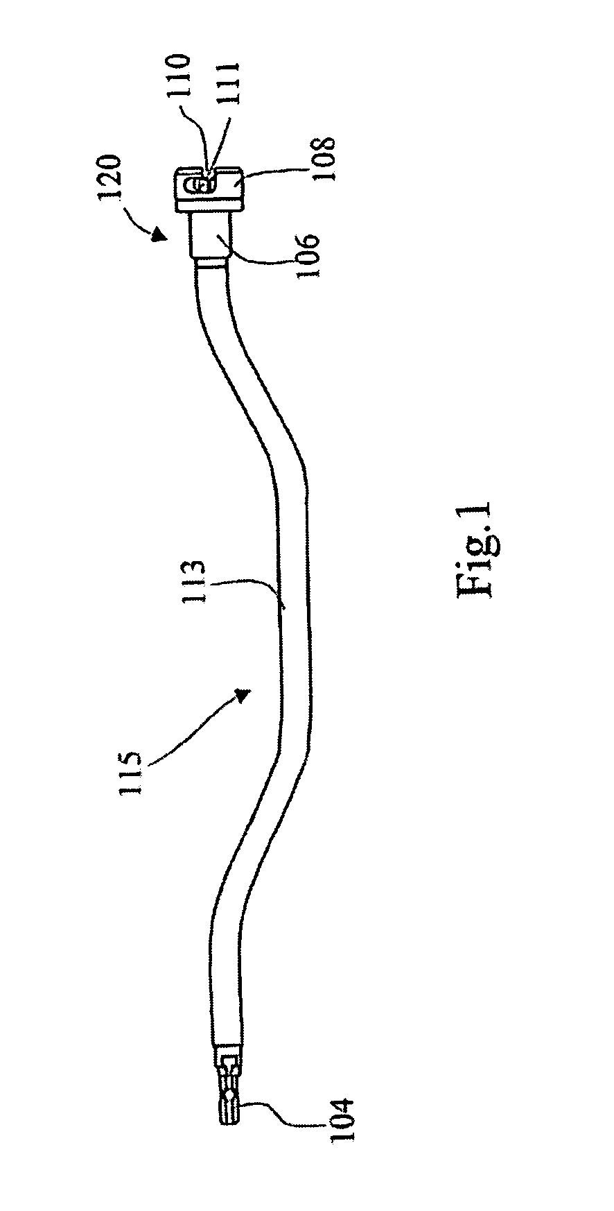
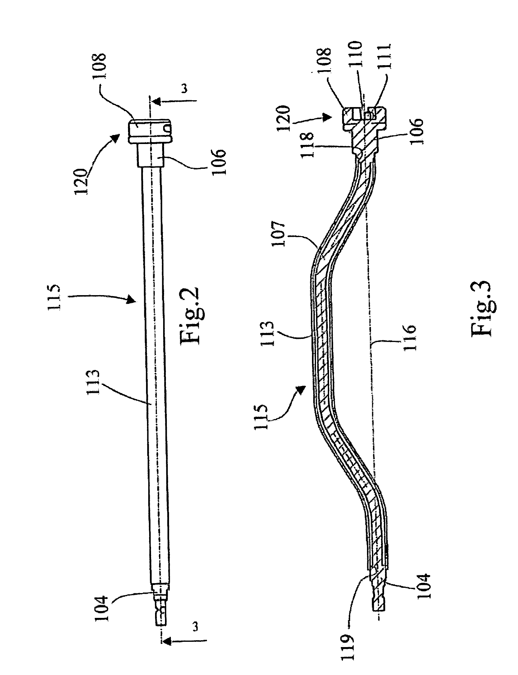
[0024] The reamer spindle 115 shown in FIGS. 1-3, and 5 consists of a drive fitting 104, which is adapted to be joined to a rotary power source used to drive the shaft 107 of the reamer spindle 115. The shaft 107 is mounted to a reamer holding mechanism 120. The reamer holding mechanism 120 can be selected from a variety of mechanisms useful for capturing and holding a surgical reamer 1 during an orthopedic surgical procedure. It is clear that many different mechanisms exist which would be useful for this task, however the present inventors have selected the preferred bayonet style mechanism 120 for purpose of example. The reamer holding mechanism 120 comprises a slide 106 carrying a pin component 111 of the reamer holding mechanism 120. The pin 111 works cooperatively with the catch 110 located in the head 108 to form the bayonet for capturing different size reamers 1 while allowing their easy release for size interchangeability and cleaning. The reamers 1 selected for use with the...


PUM


Abstract

An adjustable reamer spindle is provided to aid the surgeon in controlling the instrument. The reamer spindle is easily disassembled for cleaning. The spindle has a repositionable handle, a locking ring, and an elastic device. The elastic device biases against a handle locking mechanism that locks the repositionable handle at angular positions about an axis of the spindle. The elastic device further biases a locking ring into a locked position. The locking ring aids in holding the reamer spindle together. Removal of the locking ring against an elastic bias of the elastic means unfastens an end of the assembly in order to facilitate disassembly and/or cleaning. Adjustment of the position of the handle about the spindle enables the palm/grip of each hand to be changed in order to provide maximum control in different orientations. The adjustment is desirable in order to accommodate operating on the left or right side of the patient, standing behind or in-front of the patient, or the use of a different surgical approach. Further, adjustment is important to accommodate the differing needs of surgeons who are naturally left or right handed.

Description

CROSS REFERENCE TO RELATED APPLICATIONS [0001] This application is a continuation of prior PCT application no. PCT / 1B03 / 01725, filed 28 Apr. 2003, and claims priority thereto as well as to U.S. Provisional Applications 60 / 376,479, filed 30 Apr. 2002; 60 / 384,186, filed 30 May 2002; and 60 / 459,594, filed 2 Apr. 2003, the contents of all of which are incorporated herein by reference and relied upon.BACKGROUND OF THE INVENTION [0002] This invention relates to handles for reamers, and, more particularly, to adjustable handles for acetabular reamers that can be easily sterilized. [0003] Complicated mechanical devices have crevasses and recesses that are difficult, if not almost impossible, to clean with ease. Devices that are not properly cleaned and sterilized contribute to the risk of disease transfer from patient to patient following the emergence of certain “prions” that are not killed by normal hospital sterilisation and need to be physically removed by washing / rinsing. [0004] In GB ...

Claims


Application Information

Patent Timeline
IPC IPC(8): A61B17/16A61B17/32A61B17/56A61F2/46
CPCA61B17/1631A61B17/1633A61B2017/320032A61B19/026A61B17/1666A61B50/30A61B17/16
Inventor LECHOT, ANDREDESARZENS, YVESDAVIES, HUGHWHITE, PATRICK
Owner VIANT AS&O HLDG LLC
Why Eureka
Try Eureka