
Suture device

a technology of suture and needle, which is applied in the field of suture devices, can solve the problems of difficult extension or retracting of needles, difficult to extend or retract needles, and difficulty in deploying needles, etc., and achieve the effect of quick and easy extension

Inactive Publication Date: 2005-09-29
DAVENPORT JAMES A
View PDF8 Cites 7 Cited by
  • Summary
  • Abstract
  • Description
  • Claims
  • Application Information

AI Technical Summary

Benefits of technology

"The present invention is a suturing device that allows for quick and easy deployment of needles in tissue. The device includes a spring with elastic properties that can deform and bend outwardly from the shaft when pressure is applied to the spring. The needle and suture are attached to the spring at or near the point where the spring bends outwardly, and the spring can be designed to have a consistent point of bend each time it is tensioned. The needle can be quickly retracted when force is removed, and the device can be sized to fit through a cannula. The technical effects of the invention include improved efficiency in suturing, reduced risk of damage to organs and tissue, and ease of use in endoscopic surgery."

Problems solved by technology

However, the means for deploying the needles are often cumbersome, or the needles are deployed at an angle that is not parallel to the shaft of the suture device.
These characteristics mean that either it may be difficult to extend or retract the needle, or the needle may not be pulled perpendicularly through the tissue layer.
Unfortunately, conventional deployment mechanisms can be cumbersome and not as efficient as necessary in surgical procedures that require precision.

Method used


Image

  • Suture device
  • Suture device
  • Suture device

Examples


Embodiment Construction

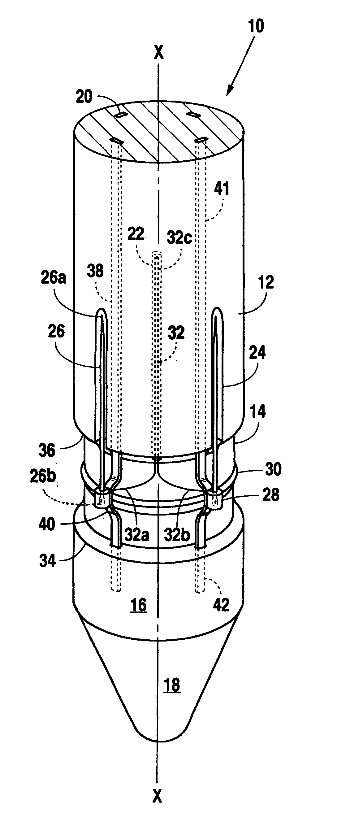
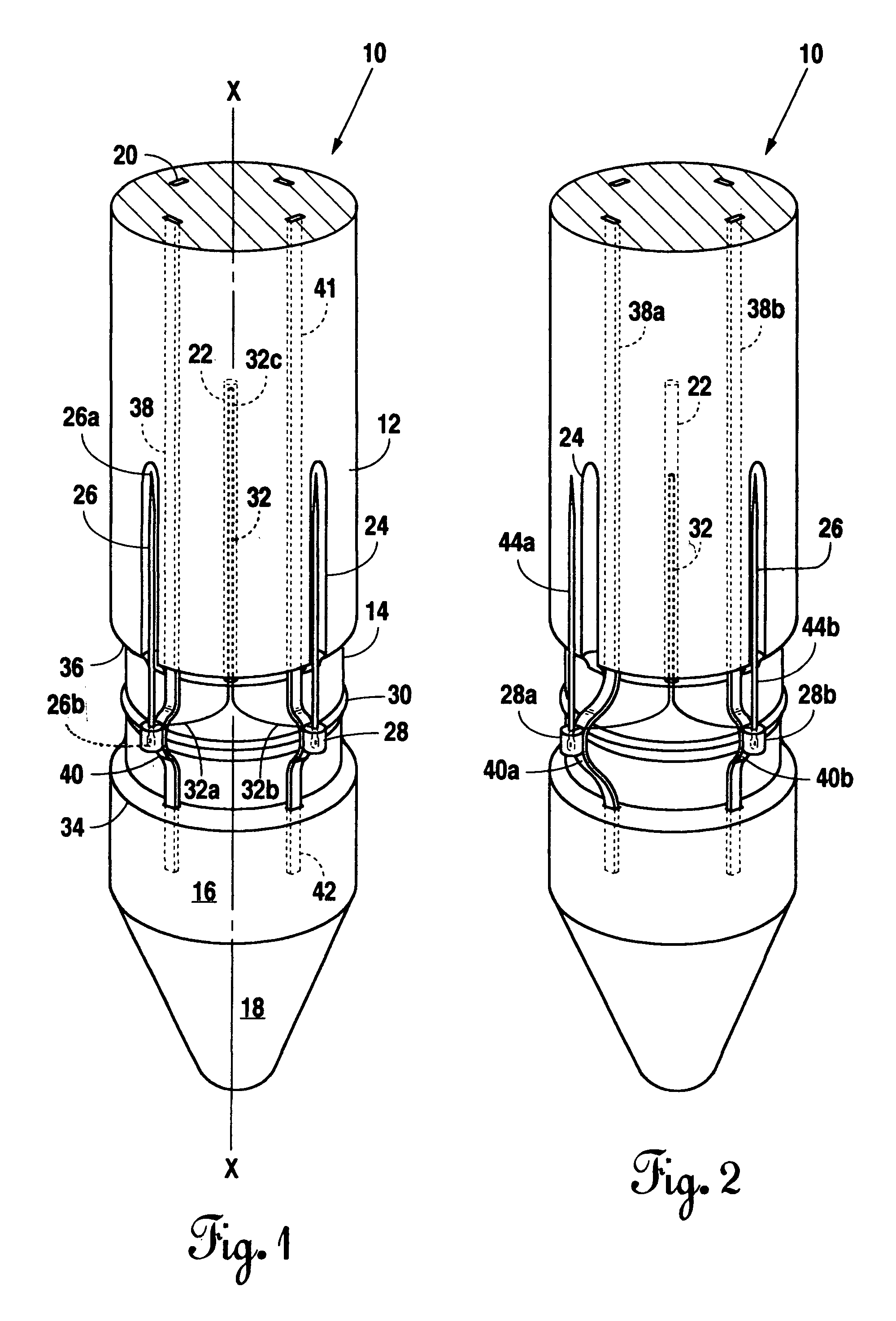
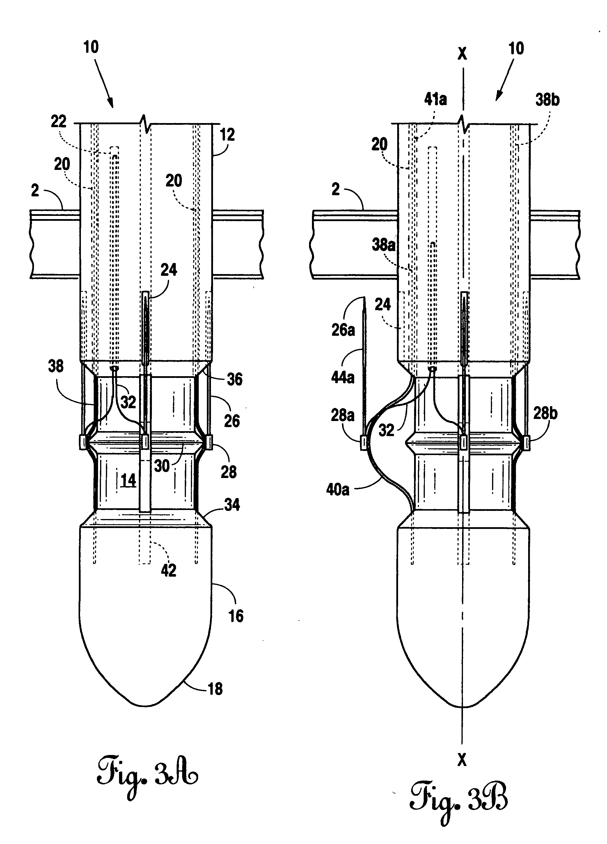
[0031] Referring to the figures, FIG. 1. illustrates the distal end of the suture device. The distal end of the suture device includes a means for extending the needle (26). The proximal end of the suture device includes a means for activating the means for extending the needle (26). However, because it is anticipated that there will be a variety of embodiments of the means for activating, a specific embodiment is not shown. The means for activating, regardless of the embodiment, is required to place a force on the spring upper portion (41) such that the spring crimped portion (40) is bent outwardly from the shaft (10).

[0032] In the portion of the suture device shown, the shaft (10) is divided into three portions, the upper shaft (12), the inner shaft (14), and the lower shaft (16). The lower shaft (16) ends in a shaft tip (18) of the distal end of the suture device. In this embodiment of the suture device, the spring (38) is a straight spring that is attached by its spring lower p...


PUM


Abstract

The present invention is a suture device generally intended for use in puncture wounds of a body cavity. The suture device can be inserted through the tissue layer into the body cavity and extend needles attached to a common suture line, under endoscopic vision, for engagement with the internal side of the tissue layer. The needles are deployed using a straight spring that deforms outwardly from the shaft of the suture device when a force is applied to the spring. Because of the inherent characteristics of the spring, it bends perpendicular to the shaft of the suture device and the removably attached needle is moved outwardly while staying generally parallel to the shaft of the suture device. Once the force is removed on the spring, the spring returns to its original position close to the body of the shaft.

Description

[0001] This application is a Continuation and claims priority from and incorporates by reference patent application Ser. No. 10 / 353 / 732 filed Jan. 29, 2003.BACKGROUND OF THE INVENTION [0002] 1. Field of the Invention [0003] Applicant's invention relates to a device for suturing together the tissue walls of body cavities that have received puncture type wounds. More particularly, it relates to a suture device that can be inserted into the body cavity through the puncture wound, extend needles connected by a suture line and draw them through the tissue walls in order to close the puncture wound. [0004] 2. Background Information [0005] Conventional instruments for closing puncture wounds generally provide for a device with a shaft that can be extended into the body cavity through the puncture wound, and then deploy needles for pulling up through the tissue walls. However, the means for deploying the needles are often cumbersome, or the needles are deployed at an angle that is not paral...

Claims


Application Information

Patent Timeline
Patent Type & Authority Applications(United States)
IPC IPC(8): A61B17/00A61B17/04
CPCA61B17/0057A61B2017/00637A61B2017/0472A61B2017/047A61B2017/00663
Inventor DAVENPORT, JAMES A.
Owner DAVENPORT JAMES A
Learn More