Method for inserting a fusion cage having a height substantially the same as the height between adjacent vertebral endplates

a fusion cage and height technology, applied in the field of improved interbody spinal fusion implants, can solve the problems of not offering the advantages associated, not being able to gain the contact between the vertebral bodies and implants needed to achieve fusion, and unwanted overdistraction of the vertebral bodies, so as to facilitate the fusion of the implants

Inactive Publication Date: 2005-09-29
WARSAW ORTHOPEDIC INC
View PDF35 Cites 54 Cited by
  • Summary
  • Abstract
  • Description
  • Claims
  • Application Information

AI Technical Summary

Benefits of technology

[0029] When the first and second implants rotate in opposite directions away from each other, the fins cut a path through the surfaces of the adjacent vertebral bodies longer than that occupied by the implant itself when deployed. This facilitates the implants being slid apart without tipping over, twisting, or moving forward or back as the fins slide sideways relative to their long axis from more central to more

Problems solved by technology

Inasmuch as the upper and lower vertebral bodies—contacting surfaces of these types of implants are arc-shaped, absent arching the recipient bed in the vertebral body by drilling, it would not be possible to gain the contact between the vertebral bodies and implant needed to achieve fusion.
While these push-in implants do have the advantage of supporting the adjacent vertebral bodies by contacting a substantial portion of the vertebral endplates, they do not offer the advantages associated with threaded cylindrical implants that are screwed into a bore in the adjacent vertebral bodies to more securely hold these implants in their final fully seated positions.
However, their cross-sectional configuration causes either unwanted over-distracti

Method used


Image

  • Method for inserting a fusion cage having a height substantially the same as the height between adjacent vertebral endplates
  • Method for inserting a fusion cage having a height substantially the same as the height between adjacent vertebral endplates
  • Method for inserting a fusion cage having a height substantially the same as the height between adjacent vertebral endplates

Examples


Embodiment Construction

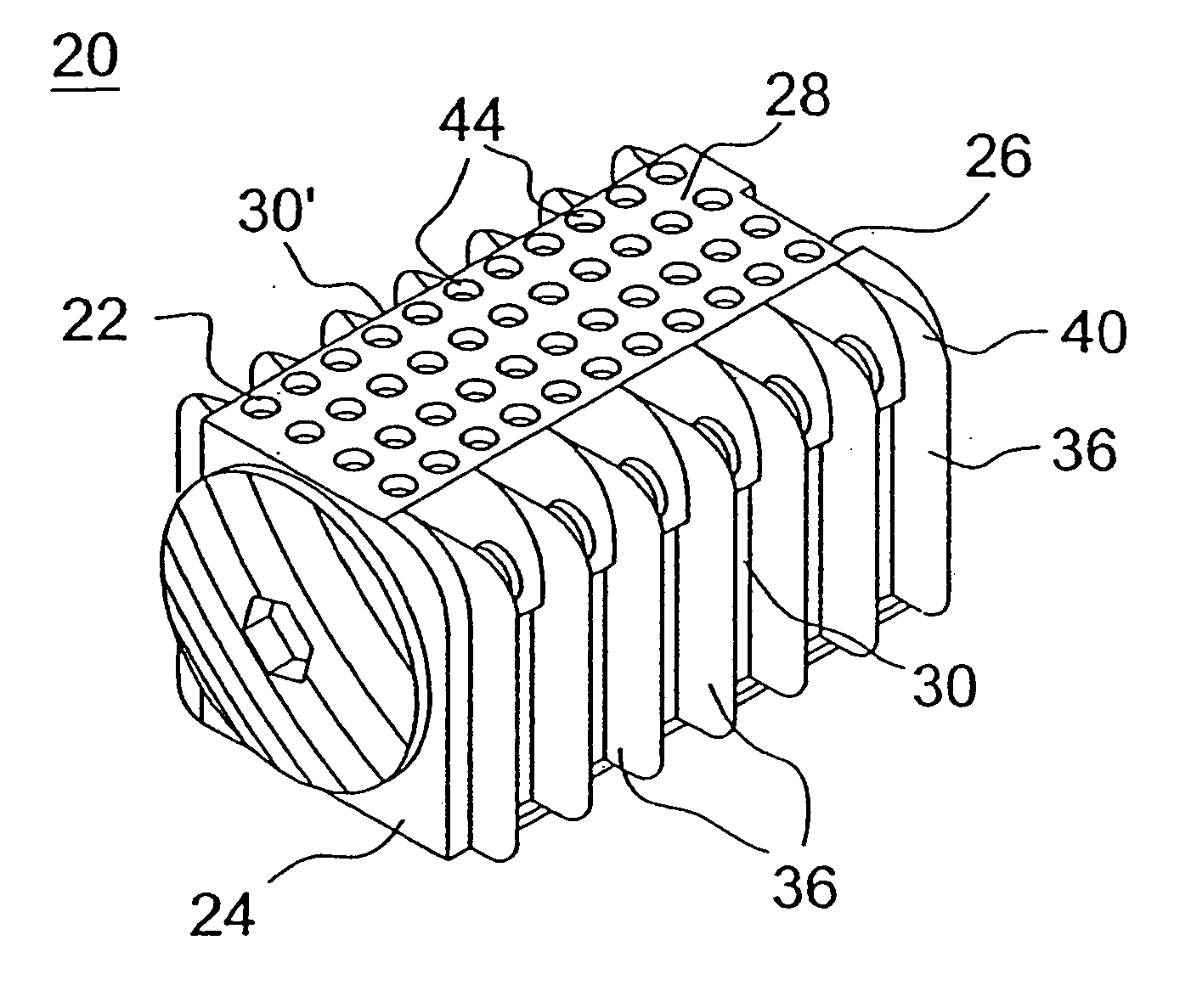
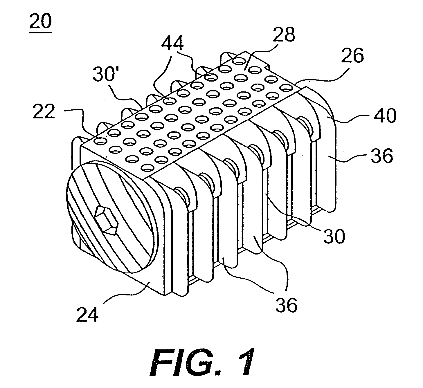
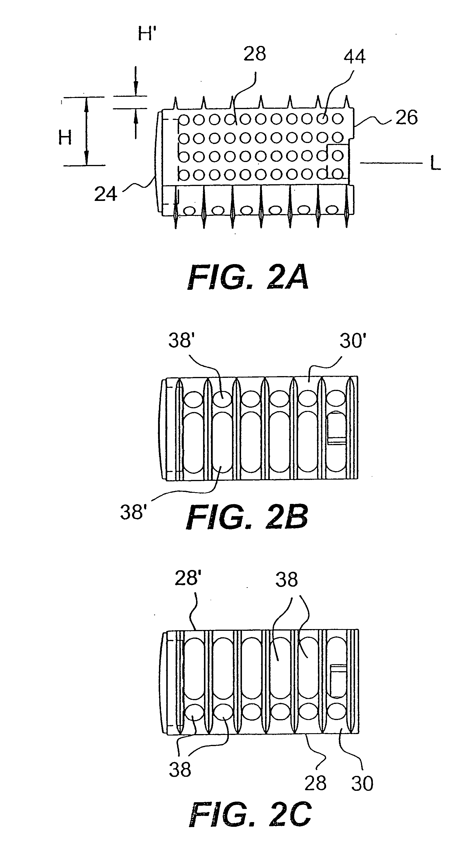
[0061] Reference will now be made in detail to the present preferred embodiments of this invention, examples of which are illustrated in the accompanying drawings. Similar reference numbers such as 28, 28′ will be used throughout the drawings to refer to similar portions of the same implant.

[0062] With reference to FIG. 1 and FIGS. 2A-2F, an interbody spinal fusion implant in accordance with a preferred embodiment of the present invention is indicated generally as 20. The implant has a body 22 having an insertion end 24, a trailing end 26, opposed side walls 28, 28′ and opposed upper and lower walls 30, 30′. Body 22 has a cross section with side walls 28, 28′ intersecting the upper and lower walls 30, 30′ at junctions that are preferably two diametrically opposed corners 32, 32′ and two diametrically opposed arcs 34, 34′. Fin-like projections 36, 36′ extend outwardly from respective ones of upper and lower wails 30, 30′ and are adapted to penetrate the vertebral endplates of the ad...


PUM

PropertyMeasurementUnit
Heightaaaaaaaaaa

Abstract

An interbody spinal fusion implant for insertion across a disc space between adjacent vertebral bodies of a human spine has a body two top side and two bottom side junctions, with at least a pair of diagonally opposed junctions having a distance therebetween that does not significantly exceed the implant body height. The implant also includes one or more bone penetrating protrusions extending outwardly from at least the upper and lower walls of the implant. The implant is inserted on its side between adjacent vertebral bodies and then rotated 90 degrees into place. The protrusions penetrate the endplates upon rotation, thereby securing the implant within the spine. The implant has at least one passage therethrough from the upper wall to the lower wall to promote fusion through the implant. Because of the specialized opposed junctions overdistraction between the adjacent vertebral bodies is avoided when the implant is rotated from an initial insertion position to a final deployed position. In one suggested implant set, two implants are rotated in opposite directions into their respective final deployed positions, and a third specialized implant is positioned therebetween to lock the three implants together along cooperating surfaces. A method for deploying the push-in implants is also disclosed.

Description

RELATED APPLICATIONS [0001] This application is a continuation of application Ser. No. 10 / 384,460, filed Mar. 7, 2003; which is a divisional of application Ser. No. 09 / 429,628, filed Oct. 29, 1999, now U.S. Pat. No. 6,537,320; which claims the benefit of U.S. Provisional Application No. 60 / 106,216 filed Oct. 30, 1998; all of which are incorporated herein by reference.BACKGROUND OF THE INVENTION [0002] 1. Field of the Invention [0003] The present invention relates generally to improved interbody spinal fusion implants for the immobilization of adjacent vertebral bodies and to a method for deployment thereof. In particular, the invention relates to interbody spinal fusion implants and methods for deployment thereof that significantly preserve the structural support of the dense endplate and subchondral bone regions of the adjacent vertebral bodies while also penetrating those endplates so as to access the vascular subchondral bone of those vertebral bodies for the purpose of achieving...

Claims


Application Information

Patent Timeline
IPC IPC(8): A61F2/00A61F2/02A61F2/28A61F2/30A61F2/44A61F2/46
CPCA61F2/28A61F2310/00359A61F2/442A61F2/446A61F2/447A61F2/4611A61F2002/2817A61F2002/2835A61F2002/2839A61F2002/30062A61F2002/30113A61F2002/30143A61F2002/30151A61F2002/30153A61F2002/3021A61F2002/30224A61F2002/30271A61F2002/30405A61F2002/30489A61F2002/3052A61F2002/30611A61F2002/30774A61F2002/30777A61F2002/30785A61F2002/30789A61F2002/30795A61F2002/30805A61F2002/30827A61F2002/30848A61F2002/30884A61F2002/30892A61F2002/30904A61F2002/4475A61F2002/448A61F2002/4485A61F2002/4638A61F2210/0004A61F2220/0025A61F2230/0006A61F2230/0017A61F2230/0019A61F2230/0067A61F2230/0069A61F2230/0082A61F2250/0063A61F2310/00017A61F2310/00023A61F2310/00029A61F2310/00179A61F2310/00293Y10S623/908A61F2/30744A61F2002/30487A61F2002/30261A61F2002/30593A61F2002/30604A61F2002/30845
Inventor MICHELSON, GARY K.
Owner WARSAW ORTHOPEDIC INC
Why Eureka
Try Eureka