Bridge overhang bracket

a technology for bridges and brackets, applied in the direction of building components, building scaffolds, domestic objects, etc., can solve the problems of inconvenient use, inconvenient use, and inability to use supporting structures having a wide range of sizes or shapes

Active Publication Date: 2005-10-06
JACKSON GEORGE W
View PDF13 Cites 22 Cited by
  • Summary
  • Abstract
  • Description
  • Claims
  • Application Information

AI Technical Summary

Benefits of technology

[0012] In another aspect, the invention provides a guardrail post holder that allows a guardrail post to be installed at a variety of angles relative to a top member of an overhang bracket. The guardrail post holder has first side adapted to be connected to the top member and a second side adapted to hold a guardrail post. The two sides are connected together through a pivot pin. A series of hol

Problems solved by technology

The inventor has observed that existing overhang brackets have various limitations that make them inconvenient to use.
For example, they may not be useful with supporting structures having a wide range of sizes or shapes, or they may have problems, such as incorrect guardrail post angle, when used in a range of applications.
They may also be difficu

Method used


Image

  • Bridge overhang bracket
  • Bridge overhang bracket
  • Bridge overhang bracket

Examples


Embodiment Construction

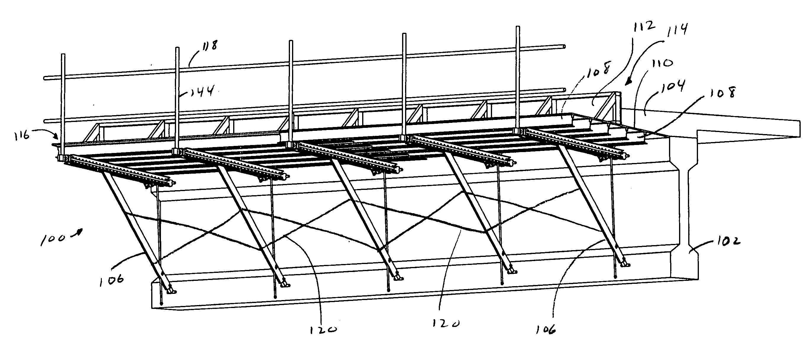
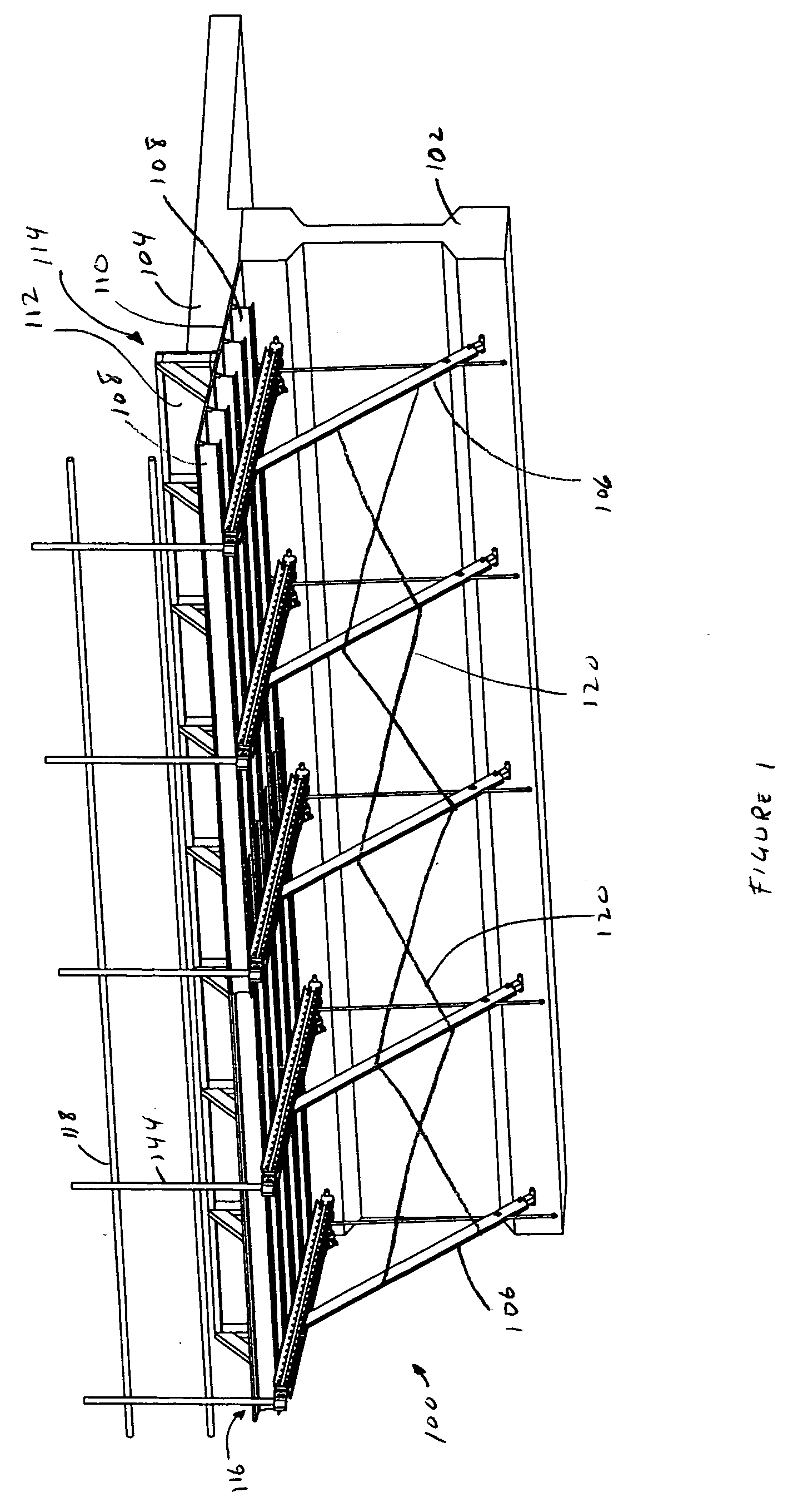
[0026] In FIG. 1, a shoring system 100 is attached to a supporting structure 102. The supporting structure 102 shown is a concrete girder supporting a concrete bridge deck 104. The shoring system 100 includes a set of overhang brackets 106 hung from the supporting structure 102. Joists 108 placed over the overhang brackets 106 support a floor 110 and a wall 112, typically made of plywood, of a form 114. A part of the area above the floor 110 is used for a walkway 116 and is bounded by a set of guardrails 118. Optional cross braces 120 may be placed between adjacent overhang brackets 106. The shoring system 100 may be assembled entirely in place or parts of the shoring system 100 may be pre-assembled on the ground. For example, overhang brackets 106, cross braces 120 and joists 108 may be assembled together into a unit and lifted, for example by a crane, in place against the supporting structure 102.

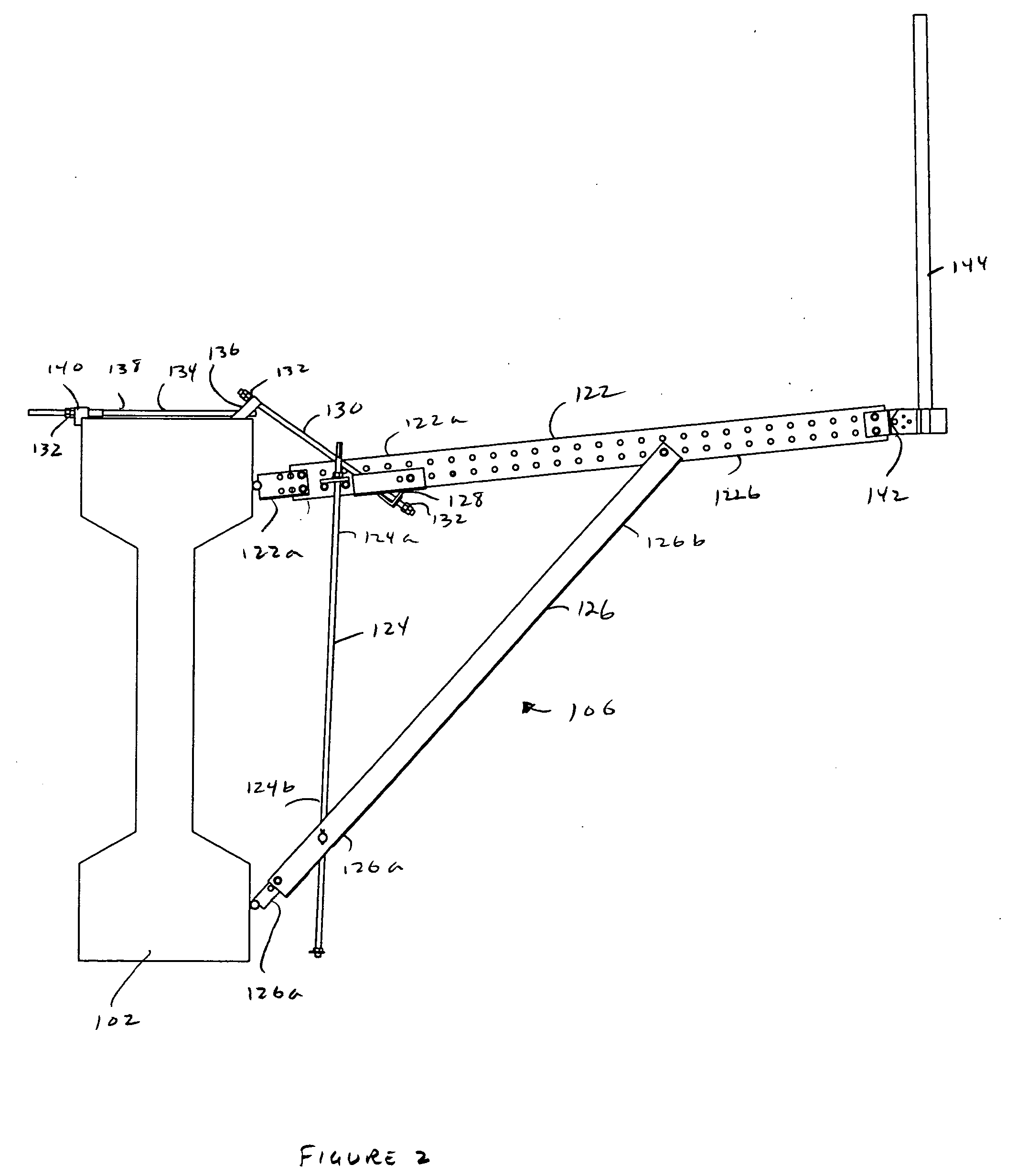
[0027] In FIG. 2, an overhang bracket 106 is hung from the supporting structure 102 ...


PUM


Abstract

An overhang bracket has a top member, a side member and a diagonal member. The side and top member may be connected together through a removable connecter. A guardrail post holder allows a guardrail post to be installed at a variety of angles to the top member. Rotating the side member causes the diagonal member to translate up or down the side member. A side member locator extends upwards from the overhang bracket to indicate the location of the side member. A tie rod holder holds a tie rod in an offset position relative to the side member. The side member locator may extend upwards through further parts of the shoring system or bridge overhang structure, for example a floor of a concrete form or rebar. A worker may adjust the overhang bracket in place from a standing position on a supporting structure or the floor of the form.

Description

[0001] This is a continuation in part of U.S. patent application Ser. No. 10 / 743,751 filed on Dec. 24, 2003 and an application claiming the benefit under 35 USC 119(e) of U.S. patent application Ser. No. 60 / 649,566 filed on Feb. 4, 2005. Both of those applications are incorporated herein in their entirety as filed by this reference to them.FIELD OF THE INVENTION [0002] This invention relates to shoring devices and more particularly to devices for shoring an overhang, for example, brackets used to support a form or mold for a concrete overhang, for example the overhanging portion of a bridge deck, a balcony or other structures. BACKGROUND OF THE INVENTION [0003] The following description of the background of the invention is not an admission that anything discussed below is citable as prior art or part of the general knowledge of workers in the field in any country. [0004] Bridges often have supporting structures, for example beams or girders, which span the length of the bridge and ...

Claims


Application Information

Patent Timeline
IPC IPC(8): E01D21/00
CPCE01D21/00
Inventor JACKSON, GEORGE W.
Owner JACKSON GEORGE W
Why Eureka
Try Eureka