Shock absorbing rope

a technology of shock absorption and rope, which is applied in the direction of safety belts, gymnastic exercise, braids, etc., can solve the problems of jumping phenomenon, application of intense reaction force to workers, and defect of conventional woven webbing 100/b>

Inactive Publication Date: 2005-10-06
YKK CORP
View PDF5 Cites 28 Cited by
  • Summary
  • Abstract
  • Description
  • Claims
  • Application Information

AI Technical Summary

Benefits of technology

[0015] The present invention has been made taking the foregoing problems into consideration and an object of which is to provide a shock absorbing rope of a simple structure whereby an ideal shock absorbing property for alleviating a shock given to a human body can be acquired and an attenuation efficiency that oscillation due to a jumping phenomenon after the shock can be attenuated so as to be made smaller is enhanced.

Problems solved by technology

Therefore, when the woven webbing 100 eases up after elongation, this results in applying of an intense reaction force to the worker.
Thus, the conventional woven webbing 100 has a defect such that a jumping phenomenon occurs.
Therefore, this structure has a problem such that the oscillation due to the reaction force after the shock of the webbing 100 cannot be made smaller by immediately attenuating it.
Therefore, this involves a problem such that manufacturing of the woven webbing 100 takes a lot of trouble and this leads to increase of its manufacturing cost or the like.

Method used


Image

  • Shock absorbing rope
  • Shock absorbing rope
  • Shock absorbing rope

Examples


first embodiment

(First Embodiment)

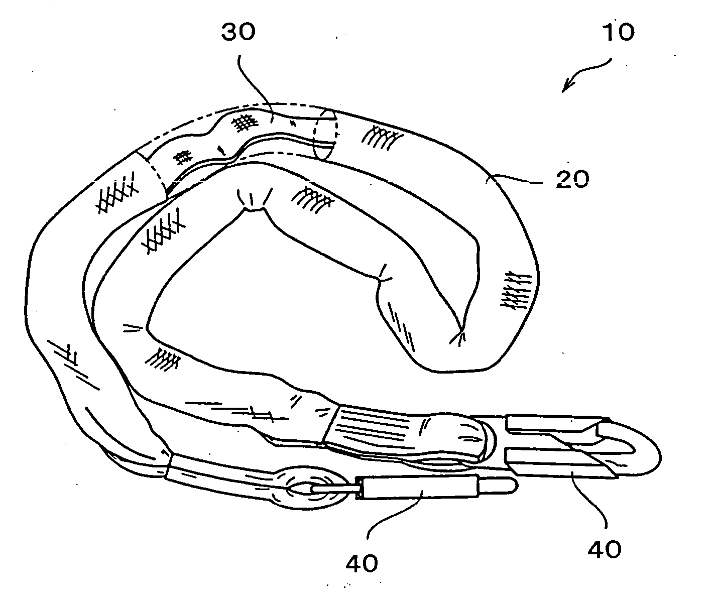
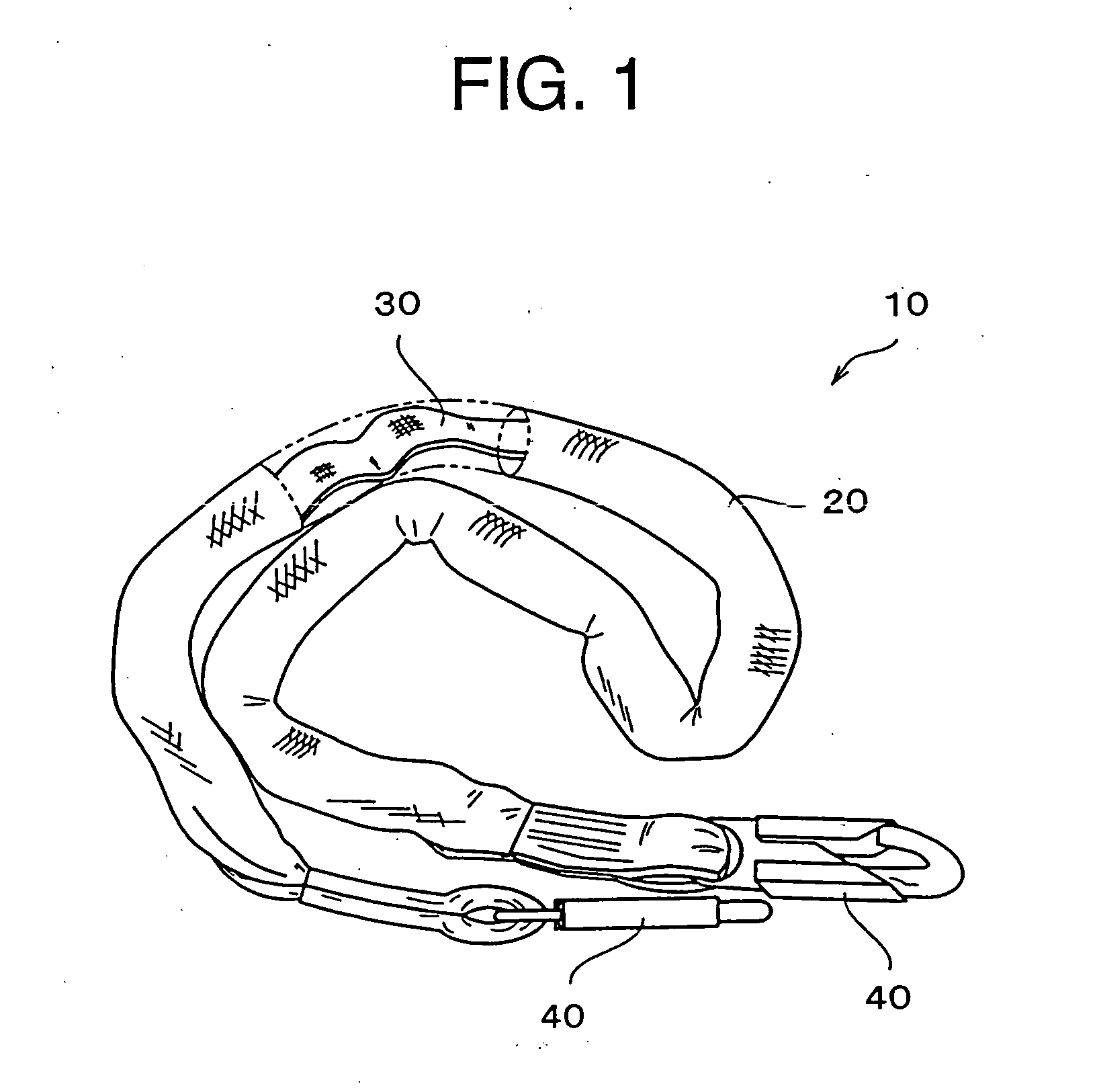
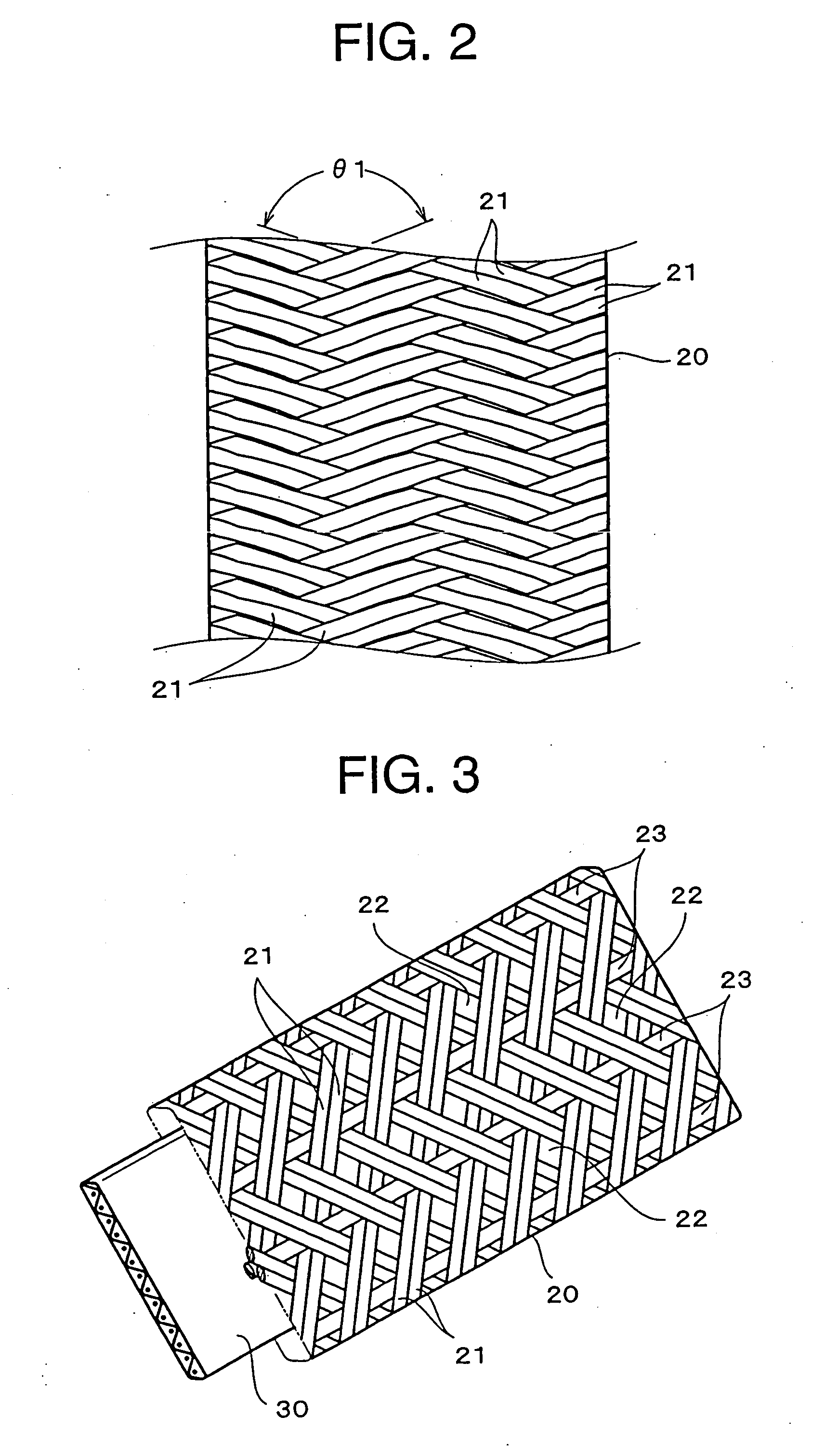
[0051] In FIG. 1, a reference numeral 10 is a pattern diagram showing a shock absorbing rope that is used as a safety member for working at the high working site having connecting fittings 40 that are fixed to the both ends of the shock absorbing rope in the longitudinal direction thereof, respectively. According to the illustrated example, a shock absorbing rope 10 forms a rope body 20 shaped in a flat and long tube and a core member 30 shaped in a narrow tape arranged inside of the rope body 20 in an eased state independently and separately from each other.

[0052] The rope body 20 is formed in a tubular hollow weaving having the core member 30 inserted through it. The both ends of the rope body 20 and the core member 30 in the longitudinal direction thereof are wrapped by the adhesive tape and the like to be formed in a taper while being elongated narrowly. The both ends of the rope body 20 and the core member 30 in the longitudinal direction thereof are folded s...

second embodiment

(Second Embodiment)

[0073]FIG. 5 a pattern diagram showing other example of the shock absorbing rope 10 according to the present invention. In the meantime, the same member names and the same reference numerals are given to the substantially same members as those in the first embodiment. Accordingly, the detailed description of these members will not be repeated here.

[0074] In this drawing, a basic configuration of the shock absorbing rope 10 is made of a general hollow woven fabric having two elastic rubbers 23 inserted on the front and rear surfaces of a long tubular rope body 20. The rope body 20 can be formed as a long tubular body by horizontally putting a weft thread row 24 into a warp thread row 21 of a synthetic fiber made of a resin material such as a polypropylene fiber, a polyester fiber, and a nylon fiber having a high intension and a high durability.

[0075] The elastic rubber 23 can be woven as a partial warp thread of the hollow woven part when weaving the rope body 20...


PUM


Abstract

The invention provides a shock absorbing rope, in which a rope body shaped in a long tube formed to be elongated in a longitudinal direction thereof and a core member arranged inside of the tube of the rope body in a eased state are formed independently and separately from each other; the both ends of the rope body and the both ends of the core member in the longitudinal direction thereof are fixed with each other; and a length of the rope body in a contraction state is shorter than a length of the core member that is not in the eased state and the core member is arranged in the tube of the rope body in the eased state, and the rope body can be elongated longer than the length of the core member that is not in the eased sate.

Description

BACKGROUND OF THE INVENTION [0001] 1. Field of the Invention [0002] The present invention relates to a shock absorbing rope whereby an ideal shock absorbing property for alleviating a shock given to a human body can be acquired. Particularly, the present invention relates to the shock absorbing rope whereby oscillation due to a reaction force after the shock can be attenuated so as to be made smaller. [0003] 2. Description of the Related Art [0004] Conventionally, for example, at a high working site such as a highrise building and a high scaffolding or the like where a worker is damaged when he or she falls down, the worker generally wears a shock absorbing rope while doing the work standing on the scaffolding. [0005] As an example of such a shock absorbing rope worn by the worker, for example, a woven webbing having a shock absorbing property is suggested (for example, refer to U.S. Pat. No. 6,085,802). A shock absorbing woven webbing 100 described in U.S. Pat. No. 6,085,802 has tw...

Claims


Application Information

Patent Timeline
Patent Type & Authority Applications(United States)
IPC IPC(8): A62B35/04E04G21/32A63B5/16D03D3/02D04C1/12
CPCA62B35/04A63B2005/163D03D3/02D07B2401/2005D07B1/02D07B2201/209D07B2201/2091D04C1/12
Inventor IKEGAMI, ISAO
Owner YKK CORP
Why Eureka
Try Eureka