Eureka AIR delivers breakthrough ideas for toughest innovation challenges, trusted by R&D personnel around the world.

Packaging device and method

a packaging device and packaging technology, applied in the field of packaging devices and methods, can solve the problems of reducing the profitability of a company, not ensuring the item, and a significant cost of packaging an article, so as to achieve less waste, less raw materials, and less cost of manufacture.

Inactive Publication Date: 2005-10-06
MAK CHI YIN
View PDF13 Cites 7 Cited by
  • Summary
  • Abstract
  • Description
  • Claims
  • Application Information

AI Technical Summary

Benefits of technology

[0014] The system of the present invention may hold objects of any shape, and provides cushioning protection to the object.
[0026] The security packaging system may be adopted to provide more secured protection to the article(s) inside it, especially for packing heavy objects or products demanding more protection. Simply by applying the same packaging method of packing a single article mentioned above to pack another packaging system by regarding that packaging system as a “wrapping”, the security can be enhanced. In other words, the packaging system may be used to house another packaging system.
[0029] If the six life buoys are replaced with six panels of closed cells, this change will not only improve the strength of the packaging, but also minimize the risk from piercing as well. Moreover, by controlling the size and configuration of individual closed cells of each panel, it can help shaping the external profile of the finished pack as well.
[0031] The inflated security packaging system consumes much less raw material as comparing with Styrofoam, PU foam, or PE foam, it is therefore much less expensive to manufacture. Moreover it takes up much less storage, handling and transportation space, creates less waste and causes less pollution.

Problems solved by technology

Packaging represents a significant cost of an article in many instances, and returns due to items broken in transit can reduce profitability for a company.
There are increasing environmental concerns regarding packing materials, and many consumers are turned off by large amounts of packing peanuts and the like in a product packaging.
Such inflatable “pillows” do not secure the item, however, but rather act only as a free cushioning device.
If the item slides to one side of the package, the pillows may no longer provide any cushioning effect.
Such a process is awkward at best, and does not insure that the cushioning amount on all sides of the article is equal.

Method used


Image

  • Packaging device and method
  • Packaging device and method
  • Packaging device and method

Examples


first embodiment

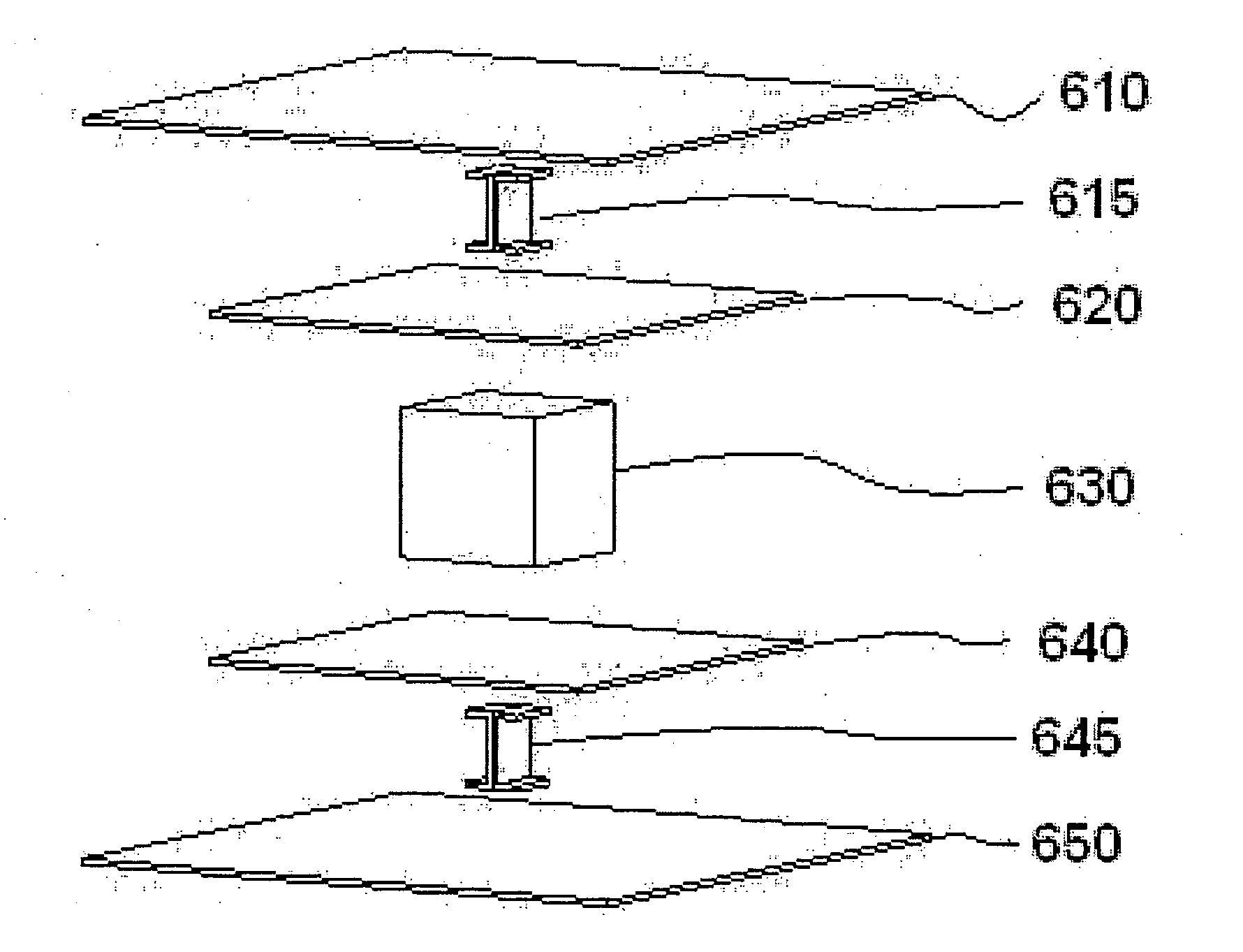
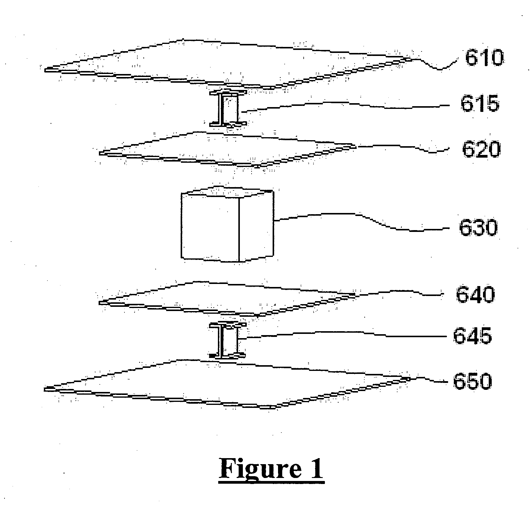
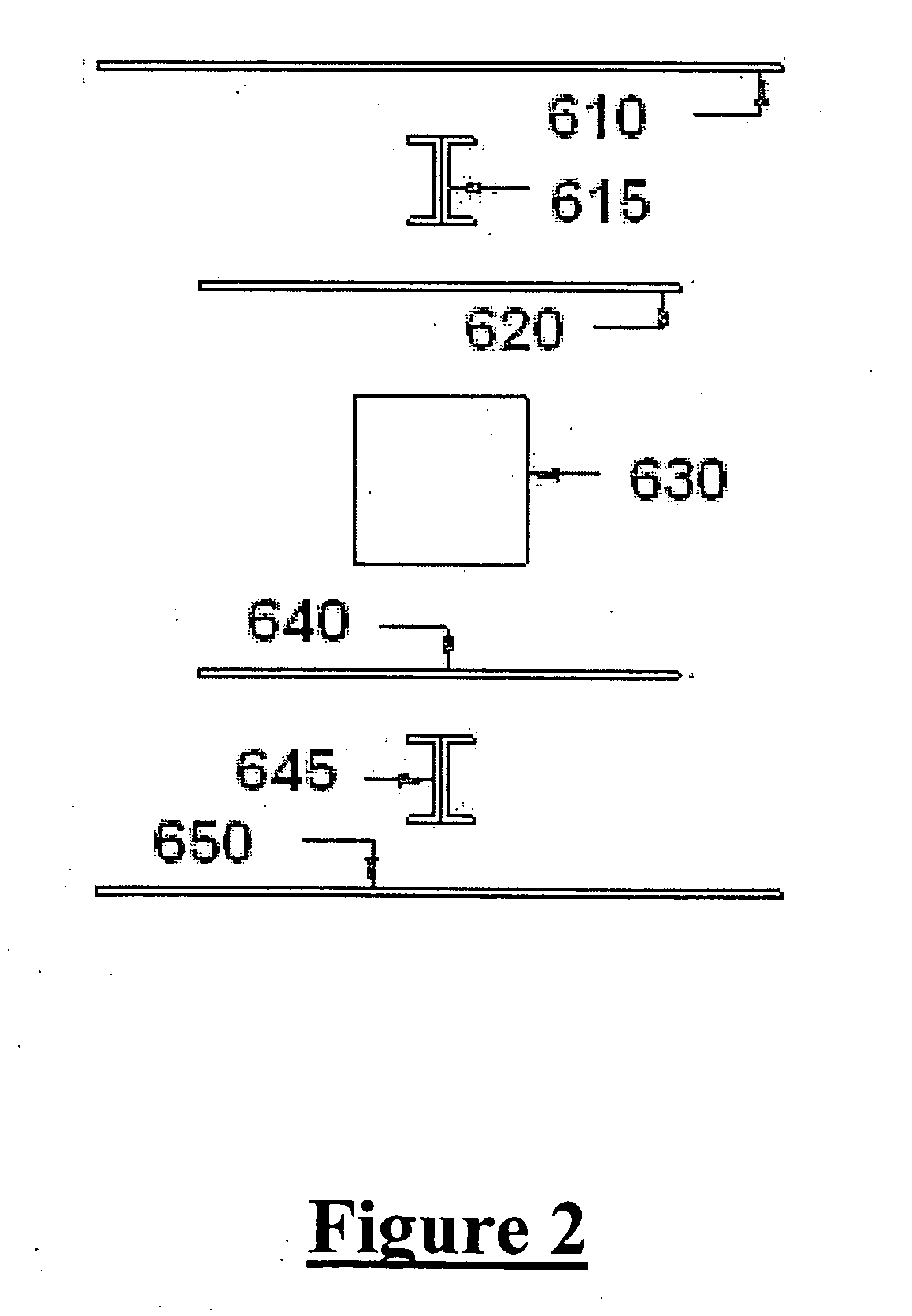
[0095]FIG. 1 is a perspective exploded view of a packaging device, generally designated as 600, according to the present invention, and FIG. 2 is a front exploded view thereof. Referring to FIGS. 1 and 2, the device 600 includes a number of component layers and linkages for securely a package article 630. The article 630 may not form part of the invention itself, but is shown for purpose of illustration as to how the invention may secure the article 630. Alternatively, the article 630 may itself be a box or package according to the present invention, with the item to be shipped placed within. As noted above, the article 630 may comprise another packaging system of the present invention, packaged within the system of the present invention.

[0096] The packaging device 600 includes an upper outer layer 610 and a lower outer layer 650, which may be formed of any type of elastomeric or resinous material, or a rigid material. In the embodiment as shown in FIGS. 1 and 2, the upper outer lay...

second embodiment

[0111]FIG. 8 is a perspective exploded view of the present invention. To simplify this exploded drawing, the linkage assemblies linking the center of the outer layers and the wrapping layers have been omitted. As noted above, the flexible linkages may be in tension, as to the flanges formed by the wrapping layer that also act as linkages. In order to achieve this requirement, wrapping layers 420 and 440 may be smaller than outer layers 410 and 450.

[0112] To overcome the size difference of the heat sealing parts, and to facilitate the heat sealing operation, a fixture comprising upper and lower portions 400 and 460 may be adopted to hold the center portion of the outer layers 410 and 450 at a certain distance from the wrapping layers 420 and 440 by means of a suction force, mechanical force, electrostatic force, sticky substances, adhesives, or the like. This center portion may be of the same size as the wrapper layers 420 and 440.

[0113] Then, the outer layers 410 and 450 and the wr...

tenth embodiment

[0131]FIGS. 27A to 27H show various views of a packaging device, generally designated as 2700, according to the present invention. An article 2702 is trapped between a smaller bag, namely one formed by the sealing of shorter sheets 2704b, 2708b, and a bigger bag, namely one formed by the sealing of longer sheets 2704a, 2708a. Air is introduced into the space between the sheets 2704b, 2708b, and that between the sheets 2704a, 2708a. The inflation pressure of the smaller bag effectively presses the article 2702 against the bigger bag, so as to isolate the article 2702 from the outer sheets 2708a, 2708b. A port 2703 is provided for evacuating the air from between the inner sheets 2704a, 2704b, or for allowing air to escape from the space between the inner sheets 2704a, 2704b during inflation of the smaller bag and the bigger bag.


PUM

PropertyMeasurementUnit
distanceaaaaaaaaaa
pressureaaaaaaaaaa
flexibleaaaaaaaaaa

Abstract

The invention basically includes an outer layer made of flexible sheets of synthetic resinous or impervious materials, and / or rigid and / or semi-rigid materials while the wrapping of each article may be held inside the packaging system by flexible linkages. The portion of the wrapping that is not directly wrapping the article should be considered as the flange of the wrapping which will become the “linkage” in the glossary of this invention. The wrapping may be designed with openings for the protruded, fragile or sharp members of the article to avoid damage to these parts. The wrapping may be made as a closed cell and a negative pressure (vacuum) may be applied to securely grasp the article. For those articles that are not suited for tight wrap, certain fluids (e.g., air) may be provided to the inside of the sealed wrapping to counteract the inflation pressure at the outside of the wrapping.

Description

FIELD OF THE INVENTION [0001] The present invention relates to a packaging device and method and, in particular, a packaging device and method for supporting and isolating an article within a unit so that the article is protected against any damage from impulsive shocks. BACKGROUND OF THE INVENTION [0002] Manufacturers have been looking for replacements to the typical prior art “packing peanuts”, newspaper, wrapping paper, shredded paper, and custom foam packing systems. Packaging represents a significant cost of an article in many instances, and returns due to items broken in transit can reduce profitability for a company. There are increasing environmental concerns regarding packing materials, and many consumers are turned off by large amounts of packing peanuts and the like in a product packaging. [0003] In some European Union countries, manufacturers are responsible for the solid waste created by packaging materials and must offer to recycle such materials or make such materials...

Claims


Application Information

Patent Timeline
Patent Type & Authority Applications(United States)
IPC IPC(8): B65B11/50B65B11/58B65B23/00B65B31/00B65B31/06B65B55/20B65D25/10B65D81/05B65D81/07B65D81/107B65D85/30
CPCB65B11/50B65B11/58B65B23/00B65D81/1075B65B55/20B65D81/052B65D81/075B65B31/06
Inventor MAK, CHI YIN
Owner MAK CHI YIN
Why Eureka
Eureka Blog
Learn More