Cap for liquid container

a liquid container and cap technology, applied in the field of caps, can solve the problems of affecting the use of known caps, affecting the safety of liquid containers,

Inactive Publication Date: 2005-10-06
ELECTROTEMP TECH
View PDF12 Cites 16 Cited by
  • Summary
  • Abstract
  • Description
  • Claims
  • Application Information

AI Technical Summary

Benefits of technology

[0006] The cap according to the invention may be used in various liquid dispensing systems, regardless of the shape of the probe, piercing spike or liquid supply tubes. The cap in accordance with this invention is efficient and inexpensive to fabricate.
[0008] In accordance with a further aspect of the invention there is provided a one piece plastic cap for use with a liquid container having a neck extending to an open mouth, said cap comprising an annular base, an outer skirt portion extending upwardly from an outer periphery of the base, said outer skirt portion and base adapted for sealing engagement over the neck and mouth of the container, a tubular portion defining a central opening in the base and extending from the base upwardly to an upper end, said tubular portion including a lid covering the upper end thereof, the lid connected to the tubular portion by a lid tear line having reduced wall thickness extending around the outer perimeter of the lid, the lid tear line being interrupted at a portion of the lid perimeter by an enhanced wall thickness portion which forms a hinge attachment between the lid and tubular portion when the lid tear line severed, and a rib of enhanced wall thickness extending from said enhanced wall thickness portion across a central portion of the lid.
[0009] In accordance with yet a further aspect of the invention there is provided a one piece plastic cap for use with a liquid container having a neck extending to an open mouth, said cap comprising an annular base, an outer skirt portion extending upwardly from an outer periphery of the base, said outer skirt portion and base adapted for sealing engagement over the neck and mouth of the container, a tubular portion defining a central opening in the base and extending from the base upwardly to an upper end, said tubular portion including a cover for the upper end thereof, the cover being pierceable, openable or selectively removable, wherein the skirt of the cap includes a skirt tear line of reduced wall thickness, extending downwardly from an upper edge of the skirt, a portion of the skirt above the skirt tear line including a pull tab defining a grip hole therein, bordering on the tear line to facilitate tearing of the skirt along the skirt tear line and thus the removal of the cap from the container.
[0010] In accordance with yet a further aspect of the invention there is provided a one piece plastic cap for use with a liquid container having a neck extending to an open mouth, said cap comprising an annular base, an outer skirt portion extending upwardly from an outer periphery of the base, said outer skirt portion and base adapted for sealing engagement over the neck and mouth of the container, a tubular portion defining a central opening in the base and extending from the base upwardly to an upper end, said tubular portion including a cover covering the upper end thereof, the cover being pierceable, openable or removable to allow flow of liquid from within the container out through the tubular portion, wherein the skirt of the cap includes a tear line of reduced wall thickness, extending downwardly from the upper edge of the skirt at an angle of no greater than approximately 40 degrees below a horizontal plane formed by the upper edge of the skirt, the portion of the skirt above the tear line including a pull tab bordering on the tear line to facilitate tearing of the skirt along the tear line and removal of the cap from the bottle.

Problems solved by technology

Several problems may arise with the use of known caps.
For example, the plug type covers may tend to disengage from the probe when urged out of contact with the tubular portion, and thereby enter the water bottle, float to the top of the water and create an undesirable aesthetic.
Additionally, lids which are designed to be pierced by the piercing spike or probe, may have pieces thereof disengage from the tubular portion, again, causing pieces to enter the water supply.
Furthermore, lids without frangible lines extending across the lid, may tend to be difficult to pierce, thereby causing undue pressure on the cap and probe, enhancing the possibility of leakage or breakage.
Known pull tab and tear line arrangements do not facilitate the easy removal of the cap from the bottle as the pull tabs may tend to be difficult to grip and the angle of the tear line, makes tearing along same somewhat difficult.

Method used


Image

  • Cap for liquid container
  • Cap for liquid container
  • Cap for liquid container

Examples


Embodiment Construction

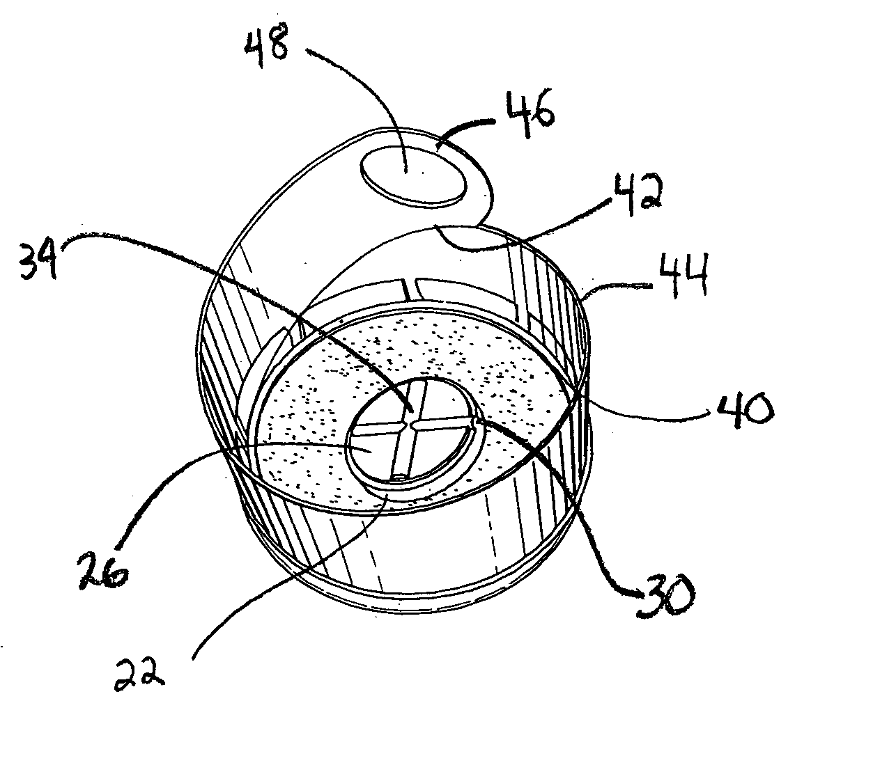
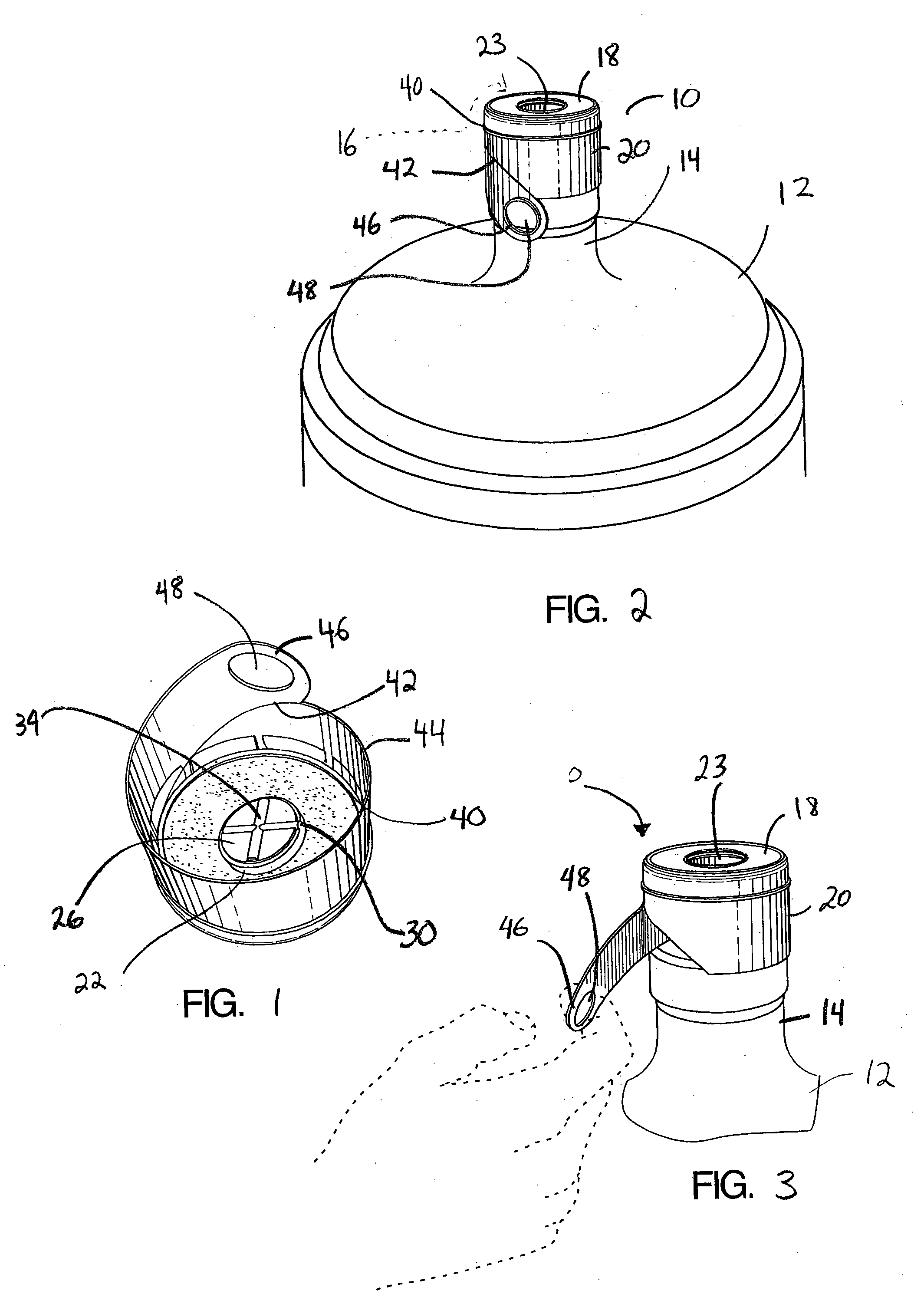
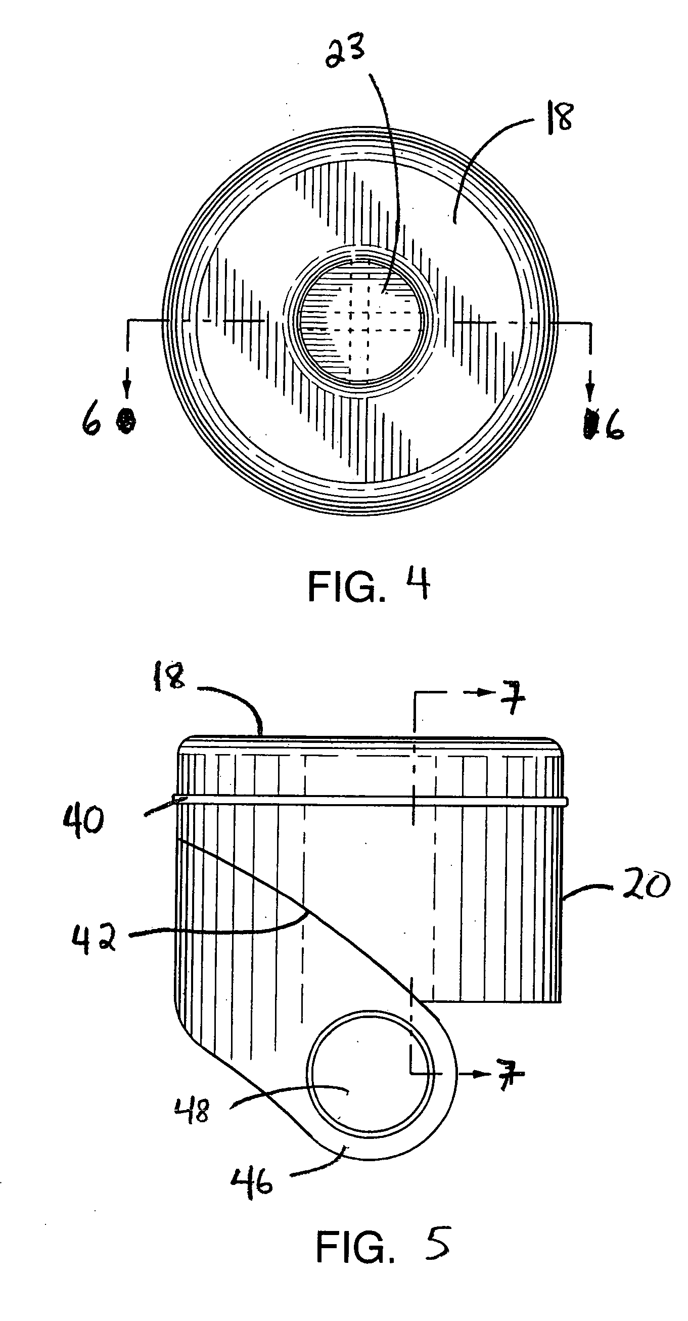
[0029] Shown in FIGS. 1 to 11 is an example embodiment of a one piece plastic cap 10, used with a liquid container 12 having a neck 14 extending to an open mouth 16. The liquid container shown is a common plastic water bottle having an 18.9L capacity, although it should be understood that the cap may adapted for utilization with bottles of various sizes and shapes. The cap 10 comprises an annular base 18, an outer skirt portion 20 which extends upwardly from an outer periphery of the base 18. As can be seen best in FIG. 2, the outer skirt portion 20 and base 18 are adapted for sealing engagement over the neck and mouth 16 of the container 12. A tubular portion 22 defines a central opening 23 in the base 18 and extends from the base upwardly to an upper end 24. When the cap is positioned over the mouth and neck of the container, the tubular portion 22 extends within the mouth 16 of the container. The tubular portion 18 includes a lid 26, which is preferably inclined, covering the upp...


PUM

PropertyMeasurementUnit
angleaaaaaaaaaa
angleaaaaaaaaaa
thicknessaaaaaaaaaa

Abstract

A one piece plastic cap is used with a liquid container having a neck extending to an open mouth. The cap has an annular base and an outer skirt portion extending upwardly from an outer periphery of the base. The outer skirt portion and base are adapted for sealing engagement over the neck and mouth of the container. A tubular portion defines a central opening in the base and extends from the base upwardly to an upper end. The tubular portion includes an inclined lid covering the upper end thereof. The lid is connected to the tubular portion by a lid tear line extending around the outer perimeter of the lid. A rib pattern extends across a central portion of the lid adding strength and enhancing the even flow of plastic when forming the lid. The lid tear line is interrupted at the upper most portion of the lid by an enhanced wall thickness portion which forms a hinge attachment between the lid and tubular portion when the lid tear line is severed from the tubular portion.

Description

FIELD OF THE INVENTION [0001] The present invention relates to a cap use to seal the mouth of a liquid container, such as a water bottle typically used in an inverted position to supply water to a water dispenser. BACKGROUND OF THE INVENTION [0002] Known water dispensing systems often involve the use of an inverted water bottle, positioned in a centrally located upper opening in the dispensing system. Commonly, these bottles have an upwardly extending neck, extending to an open mouth and have a capacity of approximately 2 to 5 gallons (7.8L to 18.9L). To dispense water, the bottle is inverted and the neck is inserted within the dispensing system opening. In order to avoid spilling of water when placing the bottle in an inverted position into the opening in the dispenser, it is well known to seal the mouth of the bottle with a cap. These caps typically include an annular base which covers the mouth and an outer skirt extending around the annular base adapted to seal the cap against t...

Claims


Application Information

Patent Timeline
Patent Type & Authority Applications(United States)
IPC IPC(8): B65D17/34B65D41/48B65D41/50B65D55/00
CPCB65D41/50
Inventor YUI, GEORGE M.
Owner ELECTROTEMP TECH
Why Eureka
Try Eureka