

Image display devices, multi-display device, and luminance management device
a multi-display device and image display technology, applied in the direction of static indicating devices, instruments, television systems, etc., can solve the problem that the regular brightness adjustment of a mechanic becomes unnecessary, and achieve the effect of convenient brightness adjustmen
- Summary
- Abstract
- Description
- Claims
- Application Information
AI Technical Summary
Benefits of technology
Problems solved by technology
Method used
Image

Examples
first embodiment
[0030] (1) Entire Structure of Multidisplay Apparatus
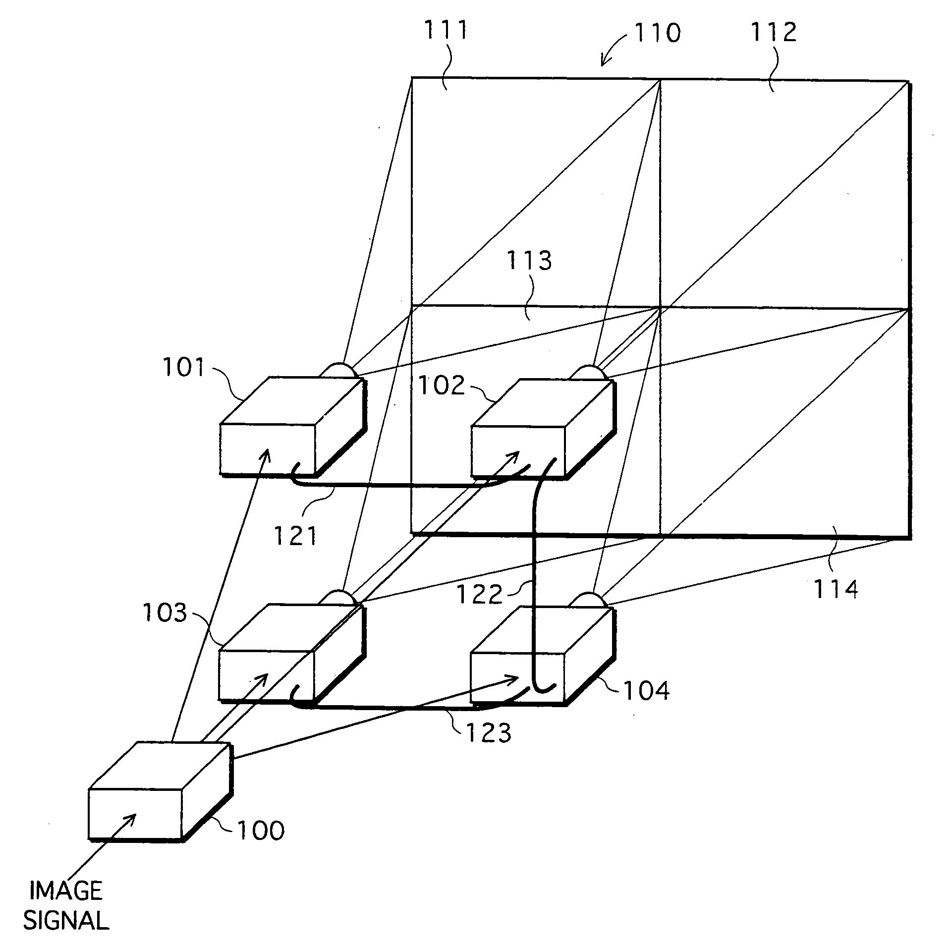
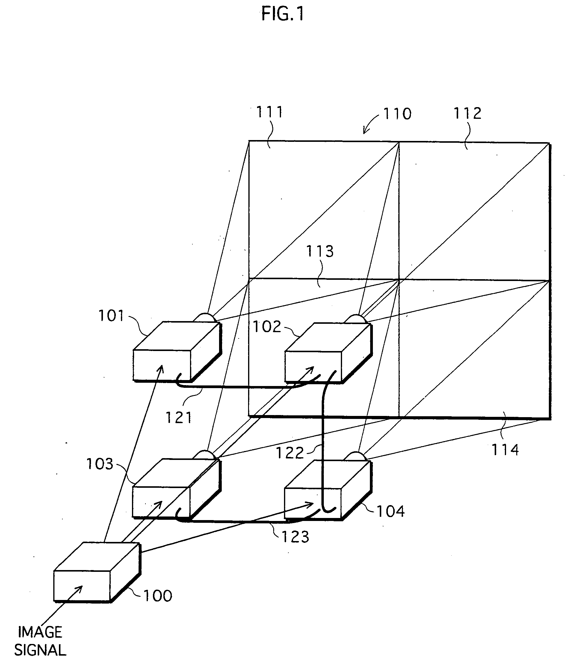
[0031]FIG. 1 shows the entire structure of a multidisplay apparatus. In the first embodiment, the multidisplay apparatus is comprised of an image distribution apparatus 100 and four projectors 101-104.
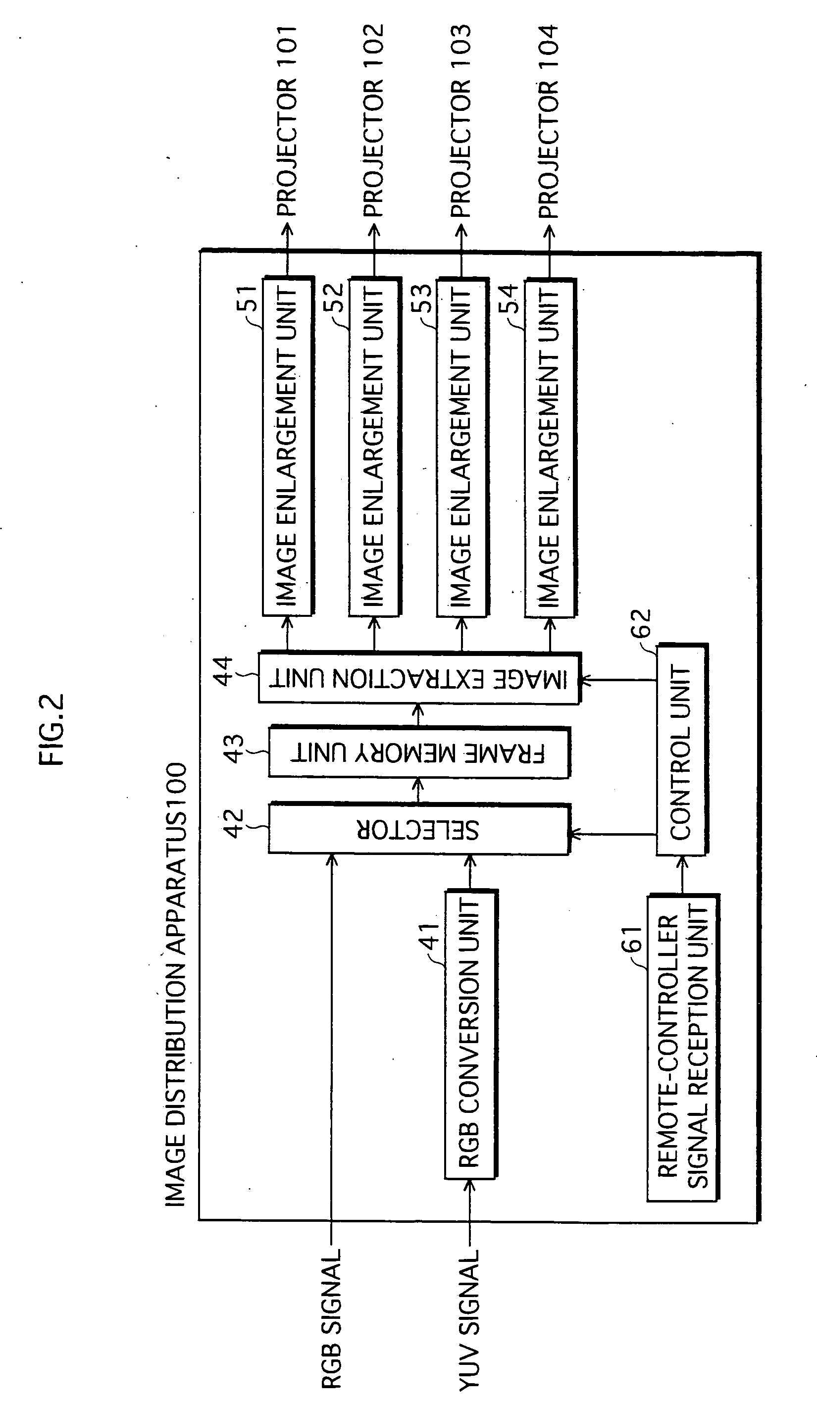
[0032] The image distribution apparatus 100 divides an image signal of one screen, which is received from a videocassette recorder or a personal computer, into four that respectively correspond to four projectors 101-104, performs predetermined signal processing such as image enlargement, to each of the four signals, and outputs the four signals after being processed to the projectors 101-104, respectively.
[0033] The projectors 101-104 are structured to form an image on their image display device according to the inputted image signal, and irradiate thereto the light from their projection lamp, thereby projecting resulting transmitted light on a screen 110 via a projection lens. Projection pictures 111-114 are provided to be adjac...
second embodiment
[0115] In the above-described first embodiment, the projectors 101-104 are designed to exchange brightness information, and to respectively perform brightness correction as necessary. In the second embodiment, the image distribution apparatus is designed to perform brightness correction.
[0116]FIG. 13 is a block diagram showing the structure of an image distribution apparatus 200 relating to the second embodiment. In this diagram, the components assigned the same reference numeral have the same structure as in the first embodiment, and so will not be described here. In the following, only the structures unique to the present embodiment are described.
[0117] As shown in FIG. 13, in the present embodiment, four brightness correction units 71-74, which correspond to the projectors 101-104, are provided in the image distribution apparatus 200, respectively behind the image enlargement units 51-54.
[0118] In addition, the brightness decreasing characteristic memory unit 63 stores a LUT s...
modification examples
[0131] So far, the present invention has been described by way of the embodiment examples. However, it is needless to say that the present invention is not limited to the concrete examples stated in the embodiments. For example, the following modification examples can be conceived.
[0132] (1) In the first embodiment stated above, the projectors are connected to each other by communication cables. However, the connection may be performed by wireless communication, such as by using a wireless LAN.
[0133] (2) In each of the above-described embodiments, the explanation is based on usage of a translucent liquid crystal projector, as an image display apparatus. However, the image display apparatus is not limited to such, and can be any display apparatus, as long as it has a projection lamp and is able to display an image adjacent to other images displayed by other image display apparatus. For example, the present invention is applicable to a reflection-type projector that uses an optical ...
PUM
 Abstract
Description
Claims
Application Information