Magneto-resistive element

a magnetic memory and magnetoresistive element technology, applied in the field of magnetoresistive elements and magnetic memory, can solve the problems of inability to obtain a sufficiently generated magnetic field, difficult localization, and serious cross-talk problem of adjacent bits or cells affected by the magnetic field

Active Publication Date: 2005-10-06
KIOXIA CORP
View PDF3 Cites 43 Cited by
  • Summary
  • Abstract
  • Description
  • Claims
  • Application Information

AI Technical Summary

Benefits of technology

[0032]FIG. 21A is a graph depicting a magneto-resistive effect of sample 1 according to Example of the invention;
[00...

Problems solved by technology

However, a magnetic field is essentially prone to spread in spatial, and thus, localization is difficult.
In the case where a specific bit or cell is selected to control its magnetization direction as the bit or cell is downsized, a “cross-talk” problem that the adjacent bit or cell is affected by the magnetic field becomes serious.
Further, if a magnetic field generation source is reduced in order to localize the magnetic field, there occurs a problem that a sufficiently generated magnetic field cannot be obtained.
Furthermore, in a recording element in which a magnetic body is provided as a medium, there is a danger that a recording state becomes unstable with respect to a disturbance referred to as a magnetic field.
There has been a fatal problem that erasure of recording or incorrect information writing occurs due to a combination of the strengt...

Method used


Image

  • Magneto-resistive element
  • Magneto-resistive element
  • Magneto-resistive element

Examples


example 1

[0181] In accordance with Example 1, a description will be given with respect to a write characteristic caused by a current charge of the magneto-resistive element according to the invention while comparing it with a write characteristic caused by a current charge of a magneto-resistive element having a free layer composed of a single magnetic layer.

[0182]FIGS. 20A and 20B are schematic views showing a sectional structure of a magneto-resistive element which the Inventor has produced as a prototype. The structure of the thus produced magneto-resistive element is as follows.

(Sample 1)

[0183] Lower electrode / [PtMn 15 nm / CoFe 4 nm / Ru 1 nm / CoFe 4 nm] / Cu 6 nm / [CoFe 1.2 nm / Ru 1 nm / CoFe 1.3 nm]

(Sample 2) [0184] Lower electrode / [PtMn 15 nm / CoFe 4 nm / Ru 1 nm / CoFe 4 nm] / Cu 6 nm / CoFe 2.5 nm

[0185] Sample 1 is provided as a magneto-resistive element in Examples of the present invention, and corresponds to the element illustrated in FIG. 16B. On the other hand, sample 2 is provided as a magn...

example 2

[0208] Now, in accordance with Example 2 of the present invention, a description will be given with respect to a result obtained by prototyping samples when magnetic fixed layers are provided on the top and bottom of the recording section.

[0209]FIGS. 27A and 27B are schematic views showing a sectional structure of a magneto-resistive element prototyped by the Inventor. A structure of the produced magneto-resistive element is as follows.

(Sample 3)

[0210] Lower electrode / [PtMn 15 nm / CoFe 4 nm / Ru 1 nm / CoFe 4 nm] / Al2O3-x 1 nm / [CoFe 1.2 nm / Ru 1 nm / CoFe 1.3 nm / Cu 6 nm / [CoFe 4 nm / Ru 1 nm / CoFe 5 nm / PtMn 15 nm]

(Sample 4) Lower electrode / [PtMn 20 nm / CoFe 20 nm] / Al2O3-x 1 nm / [CoFe 1.2 nm / Ru 1 nm / CoFe 1.3 nm] / Cu 6 nm / [CoFe 6 nm / PtMn 15 nm]

[0211] Samples 3 and 4 correspond to elements illustrated in FIGS. 17B and 18. That is, in sample 3 and sample 4 of this Example, magnetic fixed layers are provided on the top and bottom of the recording section RE, whereby an inversion current is reduced....

example 3

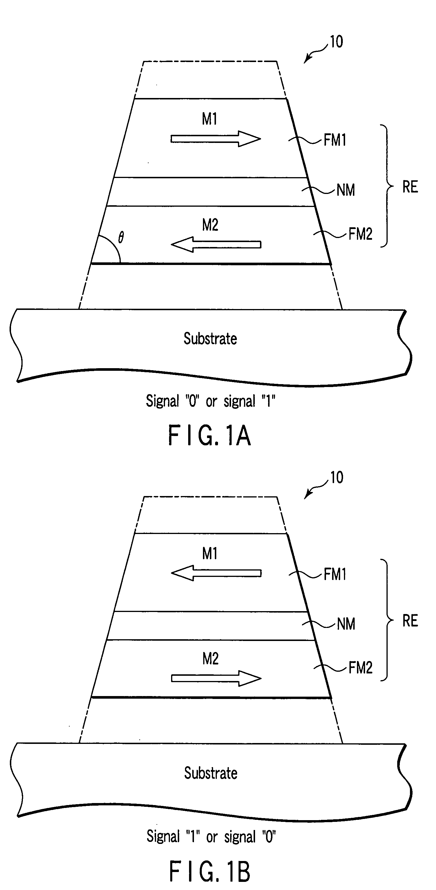
[0217] The thickness of each of the upper and lower magnetic layers configuring the recording section will be discussed in accordance with Example 3 of the present invention. An element having the structure of the invention shown in FIG. 17A in which an angle θ formed by a trapezoidal shape is 45 degrees was fabricated as sample 5. The element structure is as follows.

(Sample 5)

[0218] Lower electrode / [PtMn 15 nm / CoFe 4 nm / Ru 1 nm / CoFe 4 nm] / Al2O3-x 0.7 nm / [CoFe 1.4 nm / Ru 1 nm / CoFe 1.6 nm] / upper electrode

[0219] In addition, sample 4 having the following structure was fabricated as Comparative Example.

(Sample 6)

[0220] Lower electrode / [PtMn 15 nm / CoFe 4 nm / Ru 1 nm / CoFe 4 nm] / Al2O3-x 0.7 nm / [CoFe 1.7 nm / Ru 1 nm / CoFe 1.3 nm] / upper electrode

[0221] Sample 5 was fabricated as follows. After a lower electrode had been formed on a wafer, the wafer was introduced into a ultra-high vacuum sputtering apparatus, and a multilayer film composed of PtMn (20 nm) / CoFe 4 nm / Ru 1 nm / CoFe 4 nm / Al ...


PUM


Abstract

A magneto-resistive element comprising a free layer having two ferromagnetic layers having a nonmagnetic layer interposed therebetween are coupled with each other in an anti-ferromagnetic manner, a difference between an absolute value of a total of magnetizations of at least one ferromagnetic layer in which the magnetization direction is a first direction and an absolute value of a total of magnetizations of at least one ferromagnetic layer in which the magnetization direction is a second direction which is opposite to the first direction is equal to or smaller than 5×10⁻¹⁵ emu, and planes parallel to a substrate of the ferromagnetic layers are smaller as the planes are distant from the substrate.

Description

CROSS-REFERENCE TO RELATED APPLICATIONS [0001] This application is based upon and claims the benefit of priority from prior Japanese Patent Application No. 2004-104480, filed Mar. 31, 2004, the entire contents of which are incorporated herein by reference. BACKGROUND OF THE INVENTION [0002] 1. Field of the Invention [0003] The present invention relates to a magneto-resistive element and a magnetic memory, and more particularly, relates to a magneto-resistive element and a magnetic memory which enable writing by supplying spin-polarized electrons. [0004] 2. Description of the Related Art [0005] Conventionally, there has been employed a method for applying a magnetic field in order to control a magnetization direction of a magnetic body. For example, in a hard disk drive, a magnetization direction of a medium is reversed by a magnetic field generated from a recording head, thereby carrying out writing. In addition, in a solid magnetic memory, a cell magnetization direction is controll...

Claims


Application Information

Patent Timeline
IPC IPC(8): G11B5/127G11B5/33G11C11/15G11B5/39H01L21/8246H01L27/105H01L43/08H01L43/10
CPCH01L43/08G11B5/39H10N50/10
Inventor NAKAMURA, SHIHOHANEDA, SHIGERU
Owner KIOXIA CORP
Why Eureka
Try Eureka