Earmuff structure for headset or ear protector

a technology for ear protection and earmuffs, which is applied in the direction of earmuffs, earpiece/earphone manufacture/assembly, charging attachments/accumulators, etc., can solve the problems of inconvenient battery replacement, difficulty in welding and assembly, and time-consuming to proceed with welding and assembly, etc., to achieve clear and high-quality stereo sound, convenient battery replacement, and quick and convenient assembly

Inactive Publication Date: 2005-10-06
HAN DAVID
View PDF1 Cites 42 Cited by
  • Summary
  • Abstract
  • Description
  • Claims
  • Application Information

AI Technical Summary

Benefits of technology

[0007] A primary object of the present invention is to provide an earmuff structure for headset or ear protector. The earmuff structure includes a standardized speaker mounting plate that is detachably screwed to internally threaded seats on an inner surface of an earmuff shell after a speaker is assembled to the speaker mounting plate. Therefore, the earmuff can be more quickly and conveniently assembled.
[0008] Another object of the present invention is to provide an earmuff structure for headset or ear protector. The earmuff structure includes a speaker mounting plate having wall portions projected from a rear surface thereof by a predetermined height, so

Problems solved by technology

It is difficult and time-consuming to proceed with the welding and the assembling of the electrode plates 11 and the speakers

Method used


Image

  • Earmuff structure for headset or ear protector
  • Earmuff structure for headset or ear protector
  • Earmuff structure for headset or ear protector

Examples


Embodiment Construction

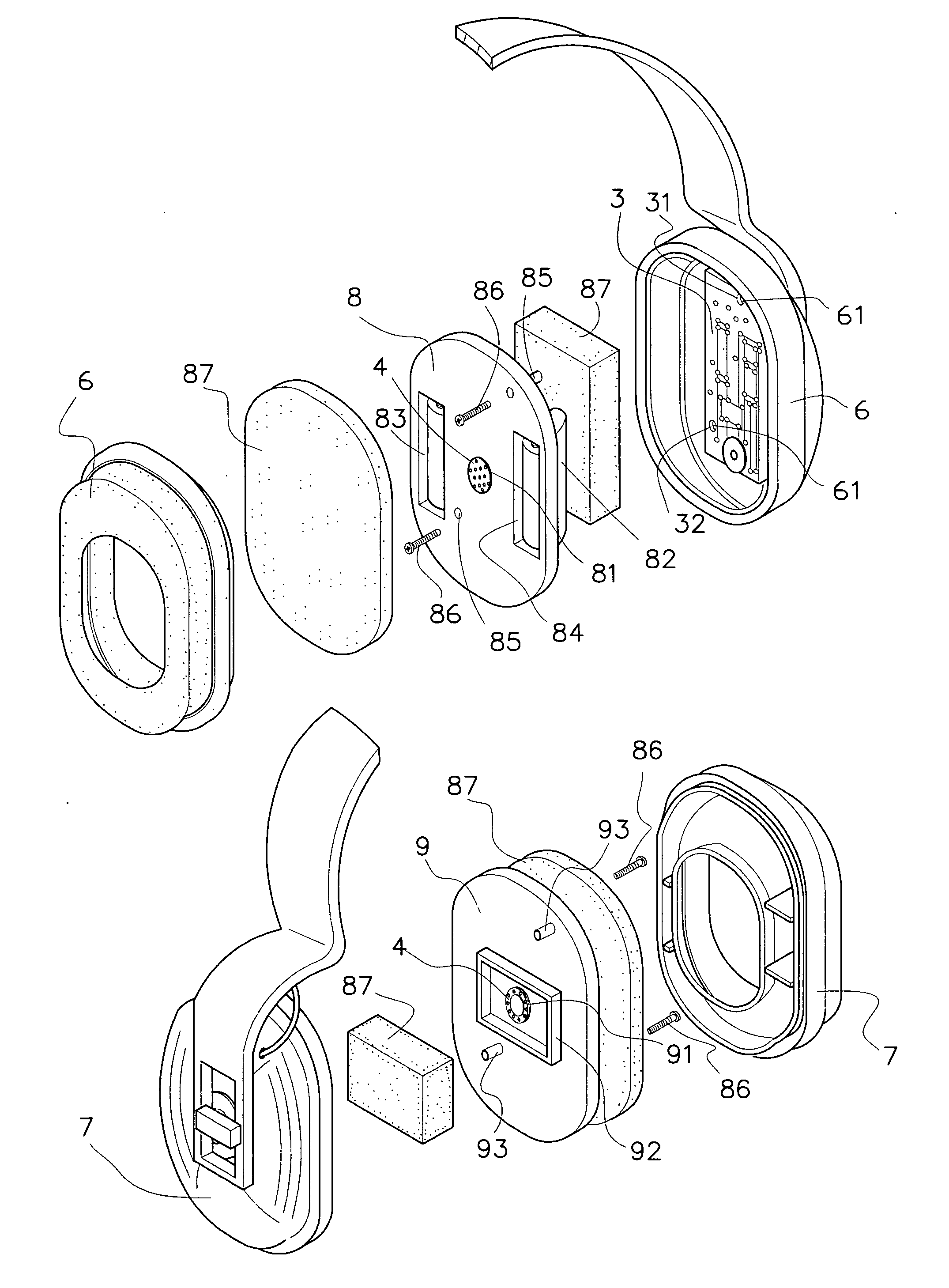
[0015] Please refer to FIG. 3 that is an exploded perspective view of a earmuff structure for headset or ear protector according to an embodiment of the present invention, and to FIGS. 4 and 5 and 6 that are partially and fully assembled perspective views, respectively, of the earmuff structure of FIG. 3.

[0016] The earmuff structure includes two earmuff shells 6, 7, and two speaker mounting plates 8, 9, which may be integrally formed by way of injection molding and respectively have a hole 81, 91 formed at a central area thereof for receiving a speaker 4 therein. The speaker mounting plates 8, 9 are provided at respective rear side with wall portions 82, 92 having predetermined heights. The wall portions 82 on the speaker mounting plate 8 are two laterally spaced walls formed from outer bottom surfaces of two rearward projected battery compartments 83, 84 at two sides of the central hole 81.

[0017] The speaker mounting plates 8, 9 are also provided at predetermined positions with t...


PUM


Abstract

An earmuff structure for headset or ear protector includes two earmuff shells and two integrally injection molded speaker mounting plates that are screwed to an inner side of the earmuff shells and each has a central hole for receiving a speaker therein. The speaker mounting plates are provided at a rear surface with wall portions of predetermined heights. The wall portions on one of the speaker mounting plates are formed from outer bottom surfaces of two battery compartments formed on a front surface of the speaker mounting plate at two sides of the central hole. With the speaker mounting plates, batteries and speakers may be quickly assembled to form the earmuffs or disassembled for replacement. The wall portions on each speaker mounting plate cooperates with a foam located behind the speaker to define a space functioning like a cabinet, creating clear and high quality stereo sounds output from the speakers.

Description

FIELD OF THE INVENTION [0001] The present invention relates to an earmuff structure for headset or ear protector, and more particularly to an earmuff structure that includes an integrally injection molded speaker mounting plate allowing quick assembling of batteries and a speaker thereto. The speaker mounting plate is provided at a rear surface with wall portions that together with a foam located behind the speaker define a space functioning like a cabinet, creating clear and high quality stereo sounds output from the speaker in the earmuff. BACKGROUND OF THE INVENTION [0002]FIGS. 1 and 2 shows a conventional earmuff structure for headset or ear protector. The conventional earmuff structure includes two earmuff shells 1 and 2, battery conducting electrode plates 11 that are directly welded to a circuit board 3 fixed in each of the earmuff shells 1, 2, and two speakers 4, each of which is fitted on a considerably small speaker mounting seat 41 having two hooking heads 42 provided at ...

Claims


Application Information

Patent Timeline
IPC IPC(8): H04R1/10H04R25/00
CPCH04R1/1008H04R5/033H04R1/1075H04R1/1025A61F11/14
Inventor HAN, DAVID
Owner HAN DAVID
Why Eureka
Try Eureka