Plastic packaging with high heat dissipation and method for the same

a high heat dissipation, plastic packaging technology, applied in the direction of transportation and packaging, other domestic articles, printed circuit non-printed electric components association, etc., can solve the problems of increasing the production cost of high heat dissipation plastic packaging, increasing the time involved, increasing the number of steps, and increasing the reliability of semiconductor elements when mounted, etc., to achieve high bonding reliability, high heat dissipation, low-profile and inexpensive

Inactive Publication Date: 2005-10-06
SUMITOMO METAL SMI ELECTRONICS DEVICES
View PDF14 Cites 5 Cited by
  • Summary
  • Abstract
  • Description
  • Claims
  • Application Information

AI Technical Summary

Benefits of technology

[0014] The object of the present invention is to overcome these problems and to provide a high heat dissipation plastic package and a method for making the same that is inexpensive, has good bonding precision, and is thin, without requiring the use of adhesive or an adhesive sheet applied afterward between the base material for forming the conductor wiring pattern and the heat dissipation plate.
[0015] Another object of the present invention is to provide a thin high heat dissipation plastic package and method for making the same that is inexpensive, has good bonding precision, and minimal bleeding of adhesive without the use of a thick adhesive sheet, e.g., a prepreg with reinforcement fiberglass cloth, between a resin substrate and heat dissipation plate. Since the prepreg with reinforcement fibers does not contain woven glass fibers, holes can be formed easily with lasers and the like. Also, since bleeding of the adhesive resin onto the cavity is prevented, a high heat dissipation plastic package can be provided with improved mounting reliability for the semiconductor element while allowing the layers to be laminated in a vacuum press.
[0016] Yet another object of the present invention is to provide a high heat dissipation plastic package equipped with a stable signal transmission system by making the heat dissipation plate exposed from the cavity electrically continuous with the conductor wiring pattern on the resin film by way of a metal layer formed on the inner wall of the cut-out for the cavity in the resin film after the Cu foil resin film has been adhesed to the heat dissipation plate.

Problems solved by technology

In the conventional high heat dissipation plastic packages and methods for making the same described above, there are the following problems.
This is an obstacle in applications where there is a need for light, thin, compact designs, e.g., in electronic devices such as mobile telephones and personal computers.
(2) If the heat dissipation plate and the base for forming the conductor wiring pattern are bonded together using an adhesive or adhesive sheet applied later, there is an increase in time involved, number of steps, and material costs for precisely applying the adhesive to the resin substrate or the heat dissipation plate or precisely attaching the adhesive sheet.
The result is increased production cost for the high heat dissipation plastic package.
(3) When bonding with an adhesive or adhesive sheet, the adhesive resin can bleed into the cavity during bonding, leading to decreased reliability when the semiconductor element is mounted in the cavity.

Method used


Image

  • Plastic packaging with high heat dissipation and method for the same
  • Plastic packaging with high heat dissipation and method for the same
  • Plastic packaging with high heat dissipation and method for the same

Examples


Embodiment Construction

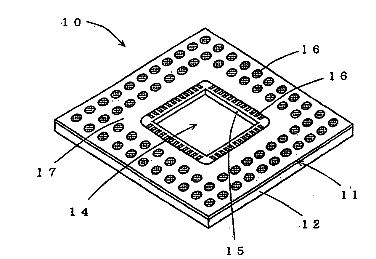
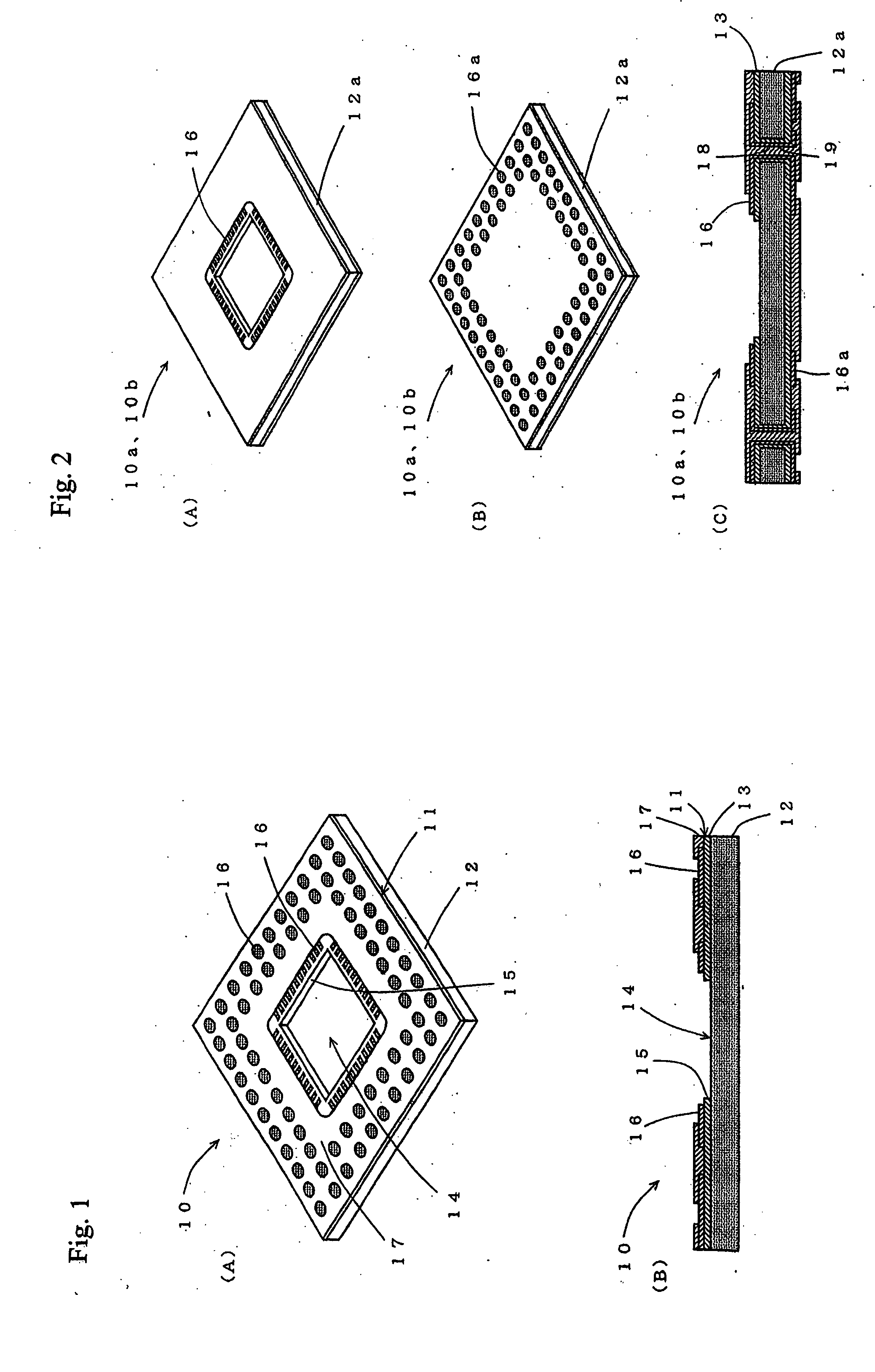
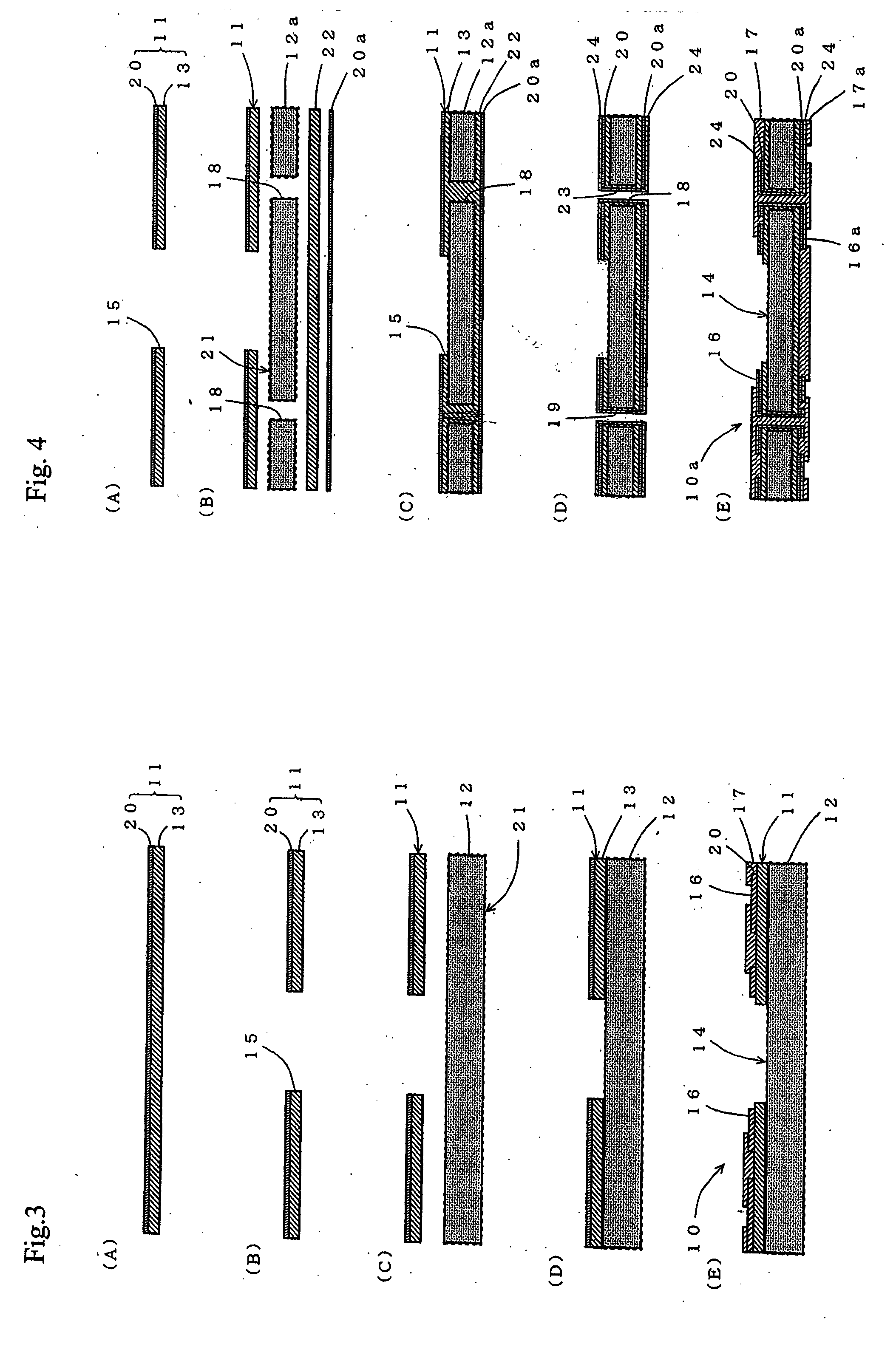
[0042] Next, embodiments of the present invention will be described in detail, with references to the drawings, to assist in the understanding of the present invention.

[0043] FIGS. 1 (A)-1(B) show, respectively, a perspective drawing and a vertical cross-section drawing of a high heat dissipation plastic package according to an embodiment of the present invention. FIGS. 2 (A)-2(C) show, respectively, an upper surface perspective drawing, a lower surface perspective drawing, and a vertical cross-section drawing of an alternative example and another alternative example of an embodiment of the present invention. FIGS. 3 (A)-3(E) are drawings for the purpose of describing a method for making a high heat dissipation plastic package according to an embodiment of the present invention. FIGS. 4 (A)-4(E) are drawings for the purpose of describing a method for making a high heat dissipation plastic package according to an alternative example of an embodiment of the present invention. FIGS. 5...


PUM

PropertyMeasurementUnit
thicknessaaaaaaaaaa
thicknessaaaaaaaaaa
temperatureaaaaaaaaaa

Abstract

The present invention provides a high heat dissipation plastic package and a method for making the same that provides an inexpensive, thin high heat dissipation plastic package with good bonding precision and minimal bleeding of adhesive resin. A Cu foil resin film is formed by bonding an adhesive resin to a Cu foil and pre-forming, at an essentially central position, a cut-out for a cavity used to mount a semiconductor element. The Cu foil resin film is bonded using the adhesive resin directly to a heat dissipation plate. A conductor wiring pattern is formed on the Cu foil resin film. Furthermore, the heat dissipation plate includes a stopping section used to prevent resin from bleeding onto a cavity when bonding with the adhesive resin of the Cu foil resin film.

Description

BACKGROUND OF THE INVENTION [0001] The present invention relates to a high heat dissipation plastic package for mounting semiconductor elements and a method for making the same. More specifically, the present invention relates to a high heat dissipation plastic package formed by adhesing a substrate for forming a conductor wiring pattern and a heat dissipation plate and a method for making the same. [0002] With the increases in performance and compactness in semiconductor elements in recent years, a variety of high heat dissipation plastic packages of the BGA (BallGridArray) type and the like have been developed. These plastic packages have been developed to handle increased heat generated by semiconductor elements, increased number of terminals used for external connections, easier mounting of semiconductor elements, lower costs, lower impedances, and the like. This type of high heat dissipation plastic package is formed by using an adhesive sheet such as a prepreg sheet to bond a ...

Claims


Application Information

Patent Timeline
Patent Type & Authority Applications(United States)
IPC IPC(8): H01L21/48H01L23/36H01L23/373H05K1/02H05K1/05H05K1/18H05K3/02
CPCH01L21/4857H01L23/36H01L23/3735H01L2924/3011H05K1/0204H05K1/021H05K1/056H05K1/182H05K3/022H05K2201/09054H05K2201/09745H05K2203/063Y10S428/901H01L2924/0002H01L2924/00Y10T428/31529Y10T428/249999Y10T428/24917Y10T428/25
Inventor TOMABECHI, SHIGEHISAHAMANO, AKIHIRO
Owner SUMITOMO METAL SMI ELECTRONICS DEVICES
Why Eureka
Try Eureka