Flexible shaft coupling

a shaft coupling and flexible technology, applied in the direction of couplings, wound springs, packaging goods types, etc., can solve the problems of increased coupling outside diameter, large stress, and inability to deflect, and achieve greater shock absorption and vibration damping performan

Active Publication Date: 2005-10-06
KYUSHU HASEC +1
View PDF10 Cites 3 Cited by
  • Summary
  • Abstract
  • Description
  • Claims
  • Application Information

AI Technical Summary

Benefits of technology

[0015] The flexible shaft coupling of the third invention is the same in the action as that of the flexible shaft coupling of the first invention. Because two coupling units are connected via the center flange, the flexible shaft coupling of the third invention adjusts twice as much offset misalignment, axial misalignment and angular misalignment of the transmission shaft as other types of flexible shaft couplings. As the torsional spring constant is ½, the flexible shaft coupling of the third invention has greater shock absorbing and vibration damping performances. A barrel-shaped stopper and an annular stopper can be fitted on the coupling.

Problems solved by technology

However, the coil springs that resist the load at each center portion of their springs perpendicularly to each spring axis, therefore receive the great stress and are not allowed to deflect greatly.
This, in turn, results in increased coupling outside diameter and increased moment of inertia.

Method used


Image

  • Flexible shaft coupling
  • Flexible shaft coupling
  • Flexible shaft coupling

Examples


Embodiment Construction

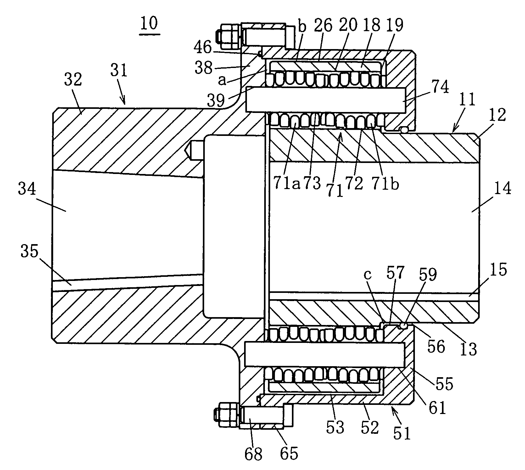
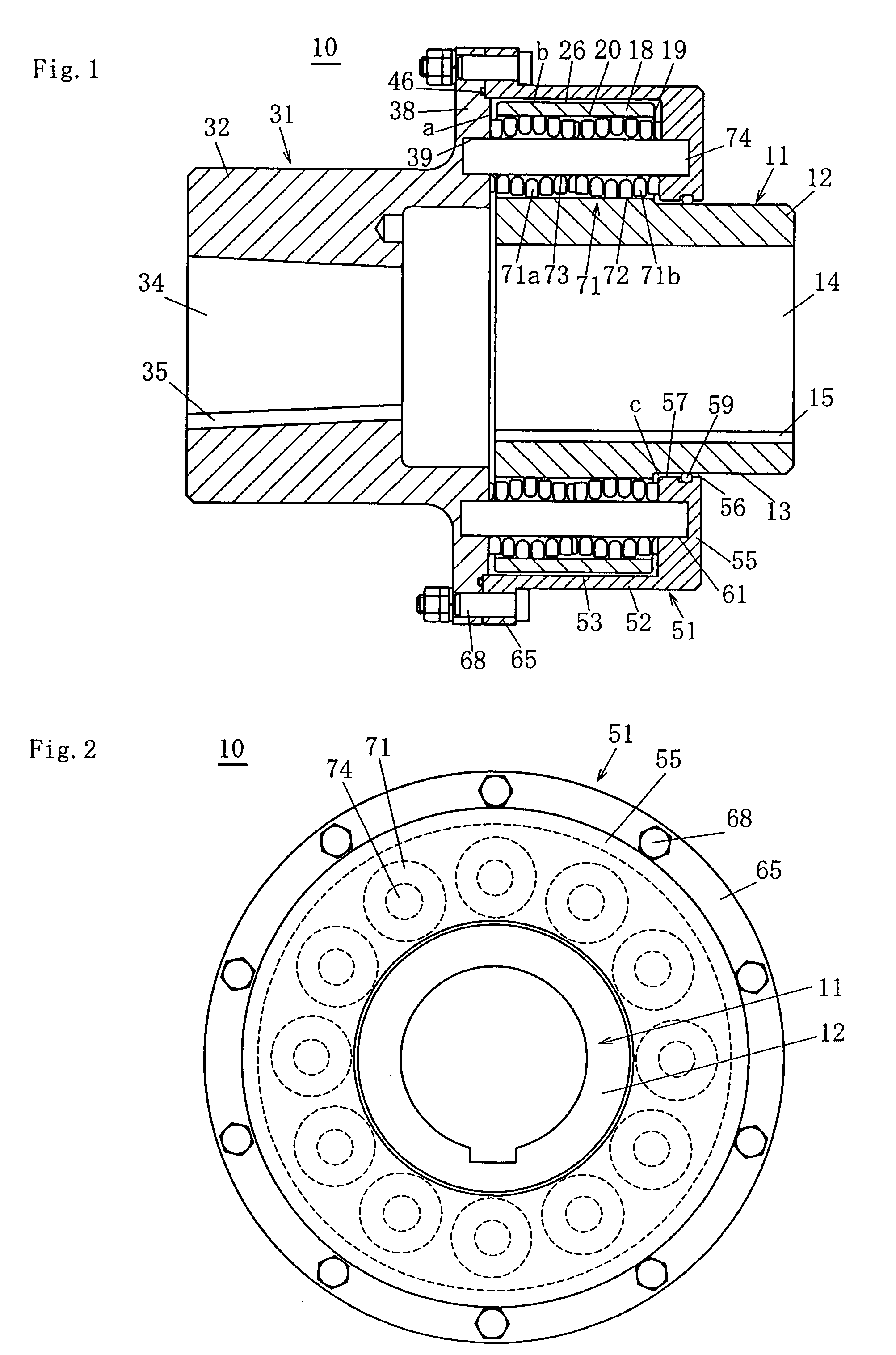
[0023]FIGS. 1 and 2 show a preferred embodiment of the first invention. FIG. 1 is a longitudinal cross-sectional view of a flexible shaft coupling and FIG. 2 is a front view of the same coupling.

[0024] A flexible shaft coupling 10 comprises a first hub 11, a second hub 31, a cover 51 and a plurality of coil spring sets 71.

[0025] The first hub 11 has a flange 18 formed at one end of the cylindrical part 12 thereof, with twelve spring holes 19 provided along the circumference of the flange 18. The cylindrical part 12 has a keyway 15 cut therein to hold a key by means of which the transmission shaft is connected to the first hub 11.

[0026] The second hub 31 has a flange 38 formed at one end of the cylindrical part 32 thereof that has a keyway 35 for connecting the transmission shaft. Spring supporting pin holes 39 corresponding to the spring holes 19 in the flange 18 on the first hub 11 are provided in the end face of the flange 38.

[0027] The cover 51 has an annular portion 55 forme...


PUM


Abstract

A flexible shaft coupling has first and second hubs, each of which is provided with flanges and connected to a transmission shaft. The flange of the first hub has spring holes extended therethrough. A cover fixed to the second hub so that the flange of the first hub is held between the cover and the flange of the second hub, and the cylindrical part of the first hub extends through the cover. A plurality of coil spring sets each comprises multiple barrel-shaped coil springs. Each of the coil springs is supported in the spring hole so that the adjoining end faces thereof are in contact and in series with each other.

Description

BACKGROUND [0001] This invention relates to a flexible coupling that effectively accommodates shaft misalignments, absorbs shock and damps vibration using coil springs as the flexible member in the torque transmitting mechanism. [0002] One type of flexible shaft coupling uses coil springs as its flexible member. In one variation of this type, the coil springs are disposed to change their shape in a direction perpendicular to the axis thereof. This type of flexible shaft coupling comprises a first and a second hub each having a flange at one end thereof and adapted for connection of the transmission shaft, a cover fastened to the flange of the second hub in such a manner as to allow passing therethrough of cylindrical part of the first hub and accommodate the flange of the first hub, and coil springs passing through each of multiple spring holes provided along the periphery of the flange of the first hub. The first and second hubs are disposed so that the flanges thereof face each ot...

Claims


Application Information

Patent Timeline
Patent Type & Authority Applications(United States)
IPC IPC(8): F16D3/70F16D3/56
CPCF16D3/56A01G7/06A01G13/0237B65D43/16B65D85/52
Inventor MIYAKAWA, TETSUYATERADO, HITOSHIFUKUDA, KAZUICHI
Owner KYUSHU HASEC
Why Eureka
Try Eureka