Positive flow valve

a flow valve and positive technology, applied in the field of medical valves, can solve the problems of clot of blood in patients, troublesome use, and life-threatening malfunctions during use, and achieve the effects of reducing dead space, reliable and repeatable performance, and simple manufacture and us

Inactive Publication Date: 2005-10-06
LOPEZ GEORGE A +6
View PDF99 Cites 79 Cited by
  • Summary
  • Abstract
  • Description
  • Claims
  • Application Information

AI Technical Summary

Benefits of technology

[0011] In general, the positive flow valve of the present invention has the attributes of safety, positive flow for eliminating dead space, reliable and repeatable performance, simplicity of manufacture and use, a seal for use in establishing fluid flow which need not be pierced with a sharp spike or cannula, suitability of high pressure applications, and employment of a valve that is swabbable after use to provide sterility and has a fluid-tight seal at high pressure.
[0012] The present invention is a swabbable, needle-less, positive flow valve that has a fluid space which automatically expands upon insertion of a medical implement and contracts upon withdrawal of the medical implement. When the valve is connected to a catheter, it induces a positive flow from the valve to the catheter tip upon disconnection of the medical implement to avoid the potential problems of blood-clogging. After use, the valve is swabbed in the conventional manner with a suitable substance to maintain sterility. The design of the valve avoids accidental needle or spike sticks. The valve is particularly suited for applications with a catheter where it is desirable to avoid backflash, but may be used for other applications as well.
[0013] Preferably, the valve includes a housing having a first end adapted for receiving one end of medical implement, and having a second end in communication with a catheter. The valve includes means for establishing a fluid flow path through the housing and between the medical implement and the catheter, and which is also useful in occluding the flow path through the housing and thereby preventing fluid flow between the medical implement and catheter.

Problems solved by technology

Connectors and valves that malfunction during use may be life-threatening.
Withdrawal of the medical implement creates a suction force which draws fluid back toward the valve in a phenomenon known as “backflash.” This is particularly troublesome in the case where the valve is connected through a catheter to a patient.
This blood clot and clog the catheter near its tip, rendering it inoperable, and may even result in a clot of blood in the patient, which may prove fatal.
Attempts to avoid backflash by coating the inner surface of the catheter near its tip in order to prevent blood from sticking to the interior surfaces of the catheter and clogging it have not been successful.
The risk of blood clogging of the catheter is significantly heightened where the inner diameter of the catheter is small (e.g., 27 gauge).
Because these catheters have a very small passage therethrough, even a small suction force may draw sufficient amount of fluid back through a catheter toward the valve to introduce blood into the catheter tip, which blood may clog the catheter's passage.
This method is clumsy and difficult, and may result in an inaccurate transfer of medicament.
The elongated portion 184, however, must be sufficiently long to displace more fluid than that volume of fluid which may be drawn from the catheter towards the valve by the withdrawal of the implement, and hence may be difficult to construct for proper performance.
In addition, this specific type of valve 180 has many significant drawbacks, among them the fact that it does not have a seal with a swabbable surface that can be swabbed after each use for sterility.

Method used


Image

  • Positive flow valve
  • Positive flow valve
  • Positive flow valve

Examples


first embodiment

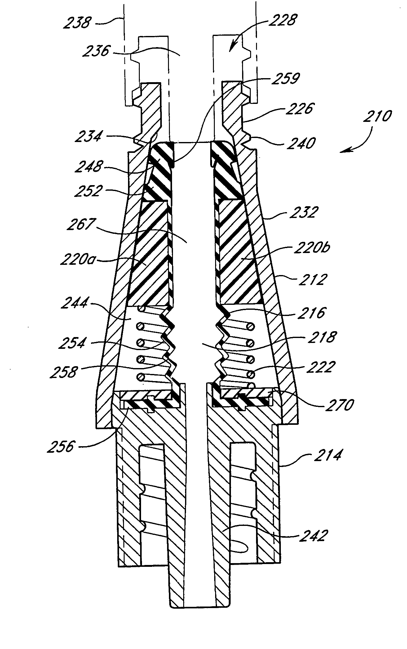
[0051]FIGS. 4 and 5 illustrate a first embodiment of a valve 210 in accordance with the present invention. In general, this valve 210 includes a valve body or housing 212, a support member 214, a seal 216 defining an inner cavity 218, a pair of clam shells 220a and 220b, and a spring 222. These components are assembled, as depicted in FIG. 4, without the need for a spike element. The inner cavity 218 forms an expandable fluid space inside the valve 210. As discussed below, the clam shells 220a / 220b are constructed to cause the volume of the fluid space to expand or increase upon insertion of a medical implement and to contract or decrease upon withdrawal of the medical implement.

[0052] The body or housing 212 has an upper conduit 226 near a proximal end 228, desirably with a circular opening 230 that is adapted to receive the medical implement. A side wall portion 232 is preferably tapered to cooperate with the clam shells 220a / 220b. The body 212 has an upper ledge 234 formed betwe...

second embodiment

[0071] In a second embodiment of the present invention illustrated in FIGS. 6 and 7, the valve 310 includes a valve body or housing 312, a support member 314, a skirt 316, a seal 318, a resilient member 320, and a pair of clam shells 322a / 322b. The housing 312 is desirably similar to the housing 212 of FIG. 4 and has a tapered side wall 324.

[0072] Referring to FIGS. 6 and 7, the second embodiment of the valve 310 has a bell-shaped skirt 316. The skirt 316 has an annular ring 328 which is disposed toward an inner conduit 330 of the support member 314. The skirt 316 creates a shield for the inner conduit 330. This inner conduit 330 is preferably cylindrical in shape and slightly tapered. The inner conduit may be connected to a terminal end of a catheter (not shown), which has an opposite, open end that is generally inserted into a patient. The support member 314 serves as a support and attachment device for the seal 318 by holding the seal 318 in place inside the housing 312.

[0073] ...

third embodiment

[0083] As shown in FIGS. 8 and 9, a third embodiment of the valve 410 of the present invention comprises a valve body or housing 412, a support member 414, a flexible tubing 416, a seal 418, a ring member 420, a pair of clam shells 422a / 422b, and a spring 424. The flexible tubing 416 may be connected to a catheter (not shown) and, together with the seal 418, defines an inner cavity 426. The inner cavity 426 forms an expandable fluid space of the valve 410. The clam shells 422a / 422b desirably are substantially the same as the clam shells 220a / 220b of FIG. 4 and are constructed to cause the fluid space within the valve 410 to increase upon insertion of a medical implement and to decrease upon withdrawal of the medical implement such as a syringe 428 partially shown in phantom in FIG. 9. The housing 412 is desirably similar to the housing 212 of FIG. 4.

[0084] The support member 414 has a hollow center 430 which supports the flexible tubing, and a proximal end 432 which encloses a dist...


PUM


Abstract

A closed system, spikeless, positive-flow valve device includes a body defining an internal cavity. At the proximal end of the body is an opening which is preferably sufficiently large to receive an ANSI standard tip of a medical implement. The valve includes a plastic, resilient silicon seal which fills the upper cavity and opening with an oval seal cap having a slit. The opening presses the oval seal cap to keep the slit closed in the decompressed state. The slit opens as the nose of the medical implement compresses the seal into the cavity and the seal cap is free from the opening. The housing also includes a fluid space which facilitates fluid flow between the medical implement and a catheter tip. The fluid space within the valve automatically and reversibly increases upon insertion of the medical implement into the cavity and decreases upon withdrawal of the medical implement, such that a positive flow from the valve toward the catheter tip is effected upon withdrawal of the medical implement, thereby preventing a flow of blood from a patient into the catheter when the medical implement is removed from the valve.

Description

[0001] This application is a continuation of pending U.S. application Ser. No. 10 / 163,719, filed Jun. 5, 2002, which is a continuation of U.S. application Ser. No. 09 / 411,988, filed Oct. 4, 1999, now U.S. Pat. No. 6,428,52, which is a continuation of U.S. application Ser. No. 08 / 767,587, filed Dec. 16, 1996, now abandoned.BACKGROUND OF THE INVENTION [0002] 1. Field of the Invention [0003] This invention relates generally to a medical valve, and in particular to a positive flow valve which, when connected between a medical implement and a catheter to facilitate fluid flow therethrough, induces a positive flow of fluid through a tip of the catheter from the valve upon disconnection of the medical implement, thereby eliminating the problem of blood-clogging or clotting in the catheter. [0004] 2. Description of the Related Art [0005] The manipulation of fluids for parenteral administration in hospitals and medical settings routinely involves the use of connectors and valves for facilita...

Claims


Application Information

Patent Timeline
Patent Type & Authority Applications(United States)
IPC IPC(8): A61M5/00A61M39/00A61M39/04A61M39/26
CPCA61M39/045A61M39/26A61M2039/263A61M2039/266A61M2039/0072A61M2039/267
Inventor LOPEZ, GEORGE A.FANGROW, THOMAS F. JR.ARNOLD, DAVID C.HUBRECHT, BRUCE M.BRUMMETT, ALISON D.GUSTUS, THOMAS J.BUI, DENNIS M.
Owner LOPEZ GEORGE A
Why Eureka
Try Eureka