Laser marking device for serial I-joist cutouts

a marking device and serial technology, applied in the direction of mechanical measuring arrangement, instruments, manufacturing tools, etc., can solve the problems of difficult marking of all individual reference points, a multitude of measurement operations, and long preparation, and achieve the effect of simple operation

Inactive Publication Date: 2005-10-13
DAVIS JOHN D
View PDF17 Cites 12 Cited by
  • Summary
  • Abstract
  • Description
  • Claims
  • Application Information

AI Technical Summary

Benefits of technology

[0007] To adjust the marker beam with respect to a predetermined final reference point on the final I-joist, a second alignment laser may be utilized in combination with a target marker having a position indicator to be aligned with the final reference point. The target marker may be temporarily affixed such that a target center of it extends vertically from the final I-joist while the position indicator is at least aligned with the final reference point. The alignment laser is at least in vertical plane with the marking laser and in an vertical offset to the marking laser extending from the initial I-joist such that the alignment beam may propagate unimpeded across adjacent I-joists. The alignment laser may be adjusted to impinge upon the target center by means of which the marking laser is brought into desired orientation at least in vertical plane with the final reference point.
[0010] The device's fixture may be either adjustable or replaceable to accommodate for varying configurations of the initial cutout. The device is simple to operate and provides a substantial improvement for precise fabrication of onsite cutouts into assembled I-joists.

Problems solved by technology

In particular, wooden hoists are assembled in architectural constructions in large numbers with small spacing, which requires a multitude of measurement operations and lengthy preparation.
With conventional laser levels well known in the construction business, the marking of all the individual reference points is difficult since the laser beam may propagate only beneath or above the I-joists.

Method used


Image

  • Laser marking device for serial I-joist cutouts
  • Laser marking device for serial I-joist cutouts
  • Laser marking device for serial I-joist cutouts

Examples


first embodiment

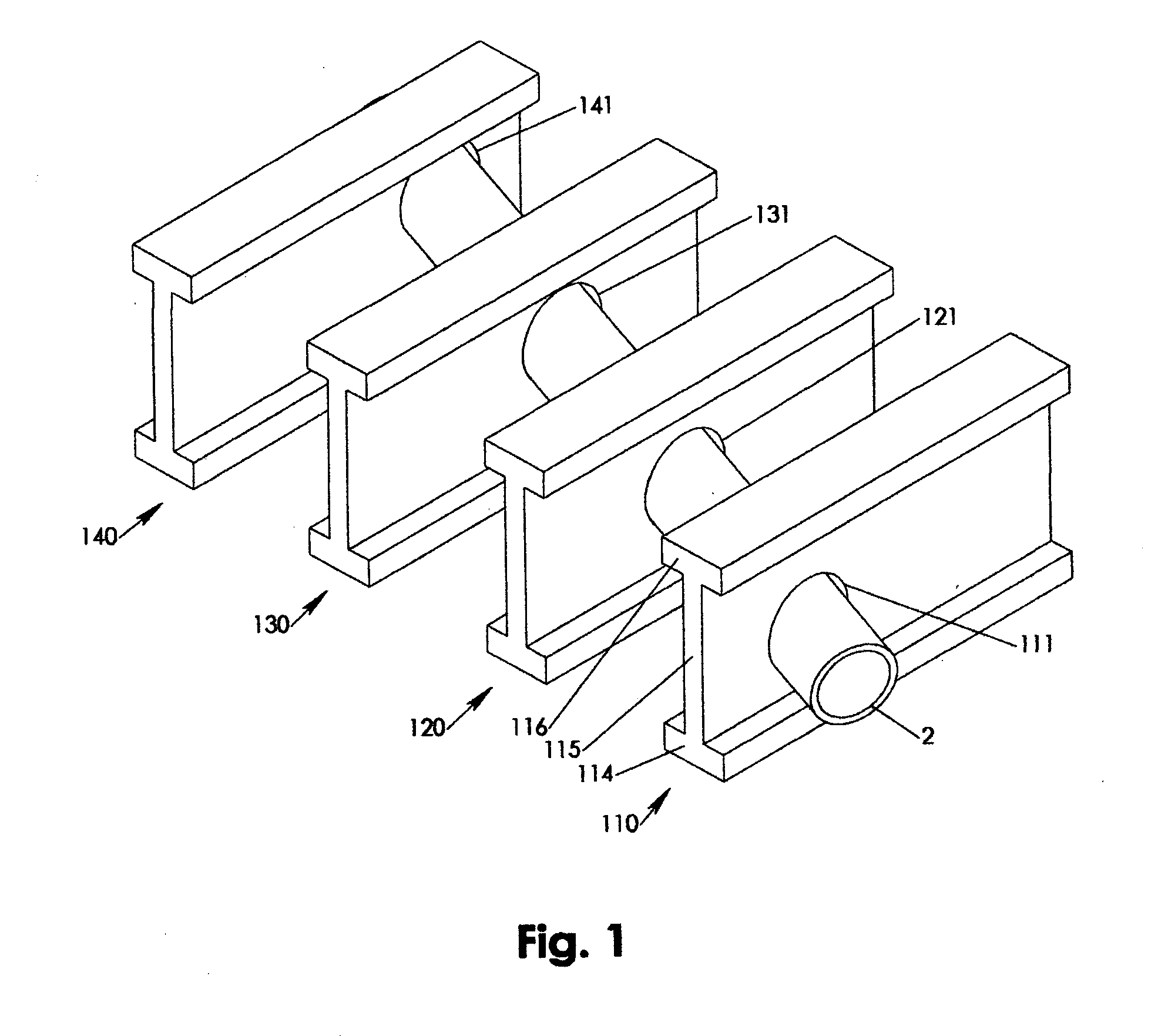
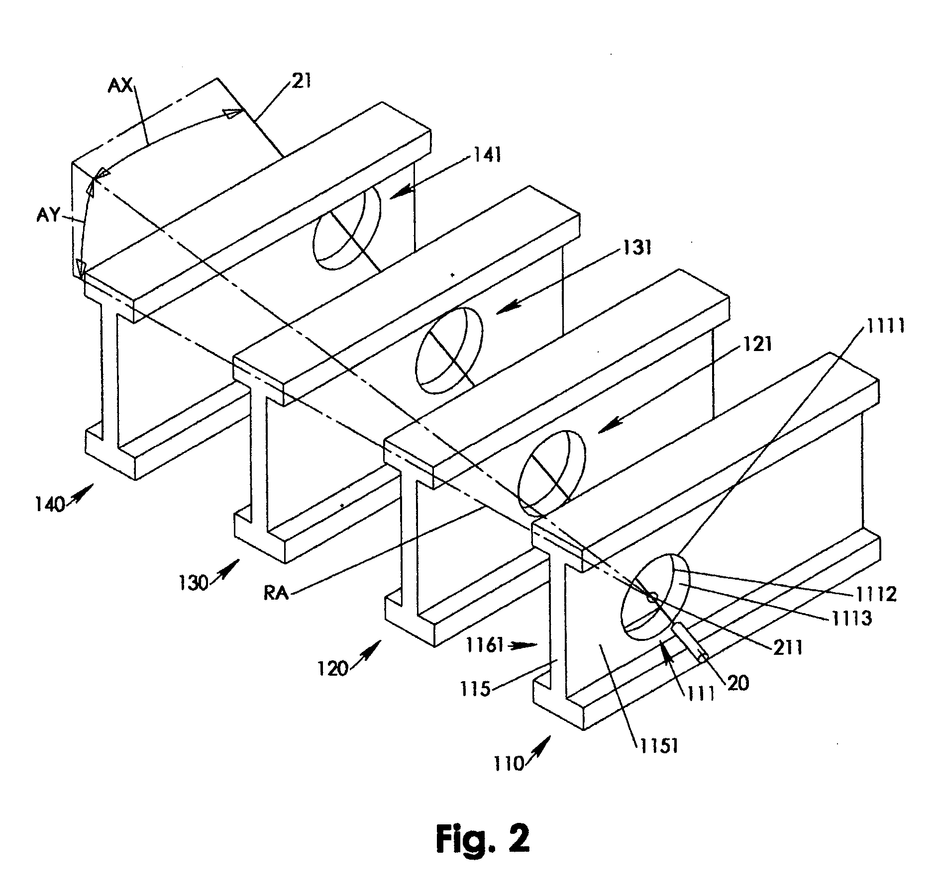
[0034] Referring to FIGS. 5-8, a laser marking device 60 includes an adjustable fixture 61 connected with a centering feature 62, which in turn holds a marking laser holder 66 via a horizontal angle gage 63 and a vertical angle gage 65. The adjustable fixture 61 has at least two spring loaded and oppositely expanding structures 613A, 613B each of which independently combined with a number of wall stops 611. As a result, the wall stops 611 are laterally forced against the cutout wall 1113 once the laser marking device 60 is inserted and released in the initial cutout 111.

[0035] The adjustable fixture 61 may additionally feature spring loaded counter stops 612 that press resiliently against the web back side 1161 while compensating for eventual burrs and other structural inconsistencies stemming from an imperfect cutting of the initial cutout 111. The forced contact between counter stops 612 and the web back side 1161 pulls the fixture 61 with the front stops 616 towards the web fron...

second embodiment

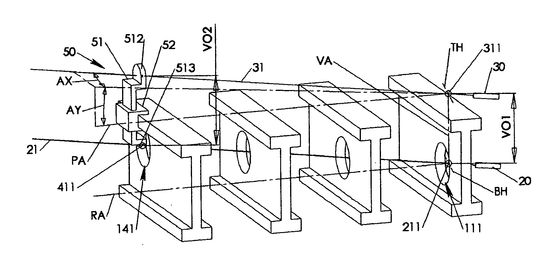
[0040] Referring to FIG. 9, a laser marking device 70 according to the invention is similar to the laser marking device 60 except that the laser marking device 70 additionally provides a holder 756 for the alignment laser 30. The alignment laser holder 756 is connected via an offset arm 751 to the vertical gage 75 such that both lasers 20, 30 are structurally coupled in their rotational movement around the vertical axis VA.

[0041] Alternatively, the offset arm 751 may be directly and only connected with the marking laser holder 76, which may couple both lasers 20, 30 in both their horizontal and vertical movements. In such case, the alignment beam 31 may coincide only with the vertical axis VA but not with the alignment origin 311, which may be negligible where vertical angle AY is only within a view degrees.

[0042] The laser marking device 70 differs from the laser marking device in as much as the laser marking device 70 may feature an level angle 717 guided in an angle guide 716 th...

third embodiment

[0043] Referring to FIGS. 10-11, a laser marking device 80 according to the invention includes an alignment laser holder 863 rotationally guided in a vertical alignment gage 851 and pivoting around a top horizontal axis TH that substantially intersects with the vertical axis VA at the alignment origin 311. The vertical alignment gage 851 is together with the vertical marking gage 852 part of a rigid dual gage body 85 that is rotationally guided by the horizontal angle gage 83 and pivoting around the vertical axis VA. The separate vertical rotations of alignment laser holder 863 and marking laser holder 862 is synchronized via connecting rod 87 hinging on a top rod pin 865 of the alignment laser holder 863 and hinging on a bottom rod pin 864 of the marking laser holder 862. As a result, the first vertical offset VO1 of marking beam 21 and alignment beam 31 remains substantially constant irrespective the vertical angle AY.

[0044] The third embodiment exemplarily demonstrates a configur...


PUM


Abstract

A laser marking device includes a fixture for temporarily attaching the device in an initial cutout of a number of serial cutouts to be fabricated in adjacent assembled I-joists. Combined with the fixture is an angle gage that provides angular positioning of a marking laser. The angle gage is configured to hold the laser with its beam coinciding with the marking origin of the initial cutout, which in case of circular cutout may be the reference center at which the pilot drill of the hole saw is centered at the begin of the cutout operation. The marker laser may be horizontally and / or vertically oriented together with an eventual alignment laser and an eventual target marker temporarily affixed on the I-joist where a final reference point is determined for an axial orientation of the cutouts across the I-joists.

Description

PRIORITY CLAIM [0001] The present Application claims priority to U.S. Provisional Application of the same title and inventor, Application No. 60 / 561,992, filed Apr. 13, 2004, which is hereby incorporated by reference. CROSS REFERENCE [0002] The present invention cross references and incorporates by reference U.S. Pat. No. 6,857,831, filed Feb. 27, 2004, titled “I-joist Hole Cutting Apparatus”.FIELD OF INVENTION [0003] The present invention relates to laser marking devices in architectural construction. More particular, the present invention relates to laser marking devices for serial I-joist cutouts. BACKGROUND OF THE INVENTION [0004] During an architectural construction process, serial cutouts need to be fabricated by construction workers into a number of adjacent assembled I-joists to provide spacing and support for piping, tubing, cabling and the like across the I-joists' web portions. In particular, wooden hoists are assembled in architectural constructions in large numbers with...

Claims


Application Information

Patent Timeline
Patent Type & Authority Applications(United States)
IPC IPC(8): G01C15/00B25H7/00
CPCB25H7/005G01C15/002
Inventor DAVIS, JOHN D.
Owner DAVIS JOHN D
Why Eureka
Try Eureka