Transformer monitoring system

a technology of transformer monitoring and transformer, applied in the direction of material analysis, emergency protective circuit arrangement, instruments, etc., can solve the problems of not reaching the set temperature, not easily determining whether the oil temperature is correct or not, and the measurement of the measured temperature after the load factor or ambient temperature change cannot be easily checked. to determine the correct temperature of the oil, the effect of high precision

Inactive Publication Date: 2005-10-13
HITACHI IND EQUIP SYST CO LTD
View PDF3 Cites 47 Cited by
  • Summary
  • Abstract
  • Description
  • Claims
  • Application Information

AI Technical Summary

Benefits of technology

[0014] It is an object of the present invention to provide a transformer monitoring system which can solve the aforementioned problems experienced with conventional systems and which can calculate with high precision an oil temperature of an o...

Problems solved by technology

In the above conventional method using a visual check, however, since an oil temperature change lags load factor and ambient temperature changes, checking the measured temperature after the load factor or ambient temperature has changed cannot easily determine if it is a proper temperature or not.
However, since the oil temperature is a sum of a temperature rise caused by a transformer loss and a temperature rise caused by the ambient temperature, if the ambient temperature is low, the oil temperature will not reach the set temperature even during an overload operation.
This method therefore could not decide whether the oil temperature is correct or not.
Nor can the conventional monitoring system determine if the oil temperature is correct or not.
Further, since the above conventional technique uses a measured value for the ambient temperature in determining the maximum winding temperature, the fact is not taken into account that an oil temperature c...

Method used


Image

  • Transformer monitoring system
  • Transformer monitoring system
  • Transformer monitoring system

Examples


Embodiment Construction

[0023] Now, a best mode embodying the present invention will be described in the following.

[0024] A system for monitoring an oil-filled transformer as one embodiment of this invention will be described by referring to the accompanying drawings.

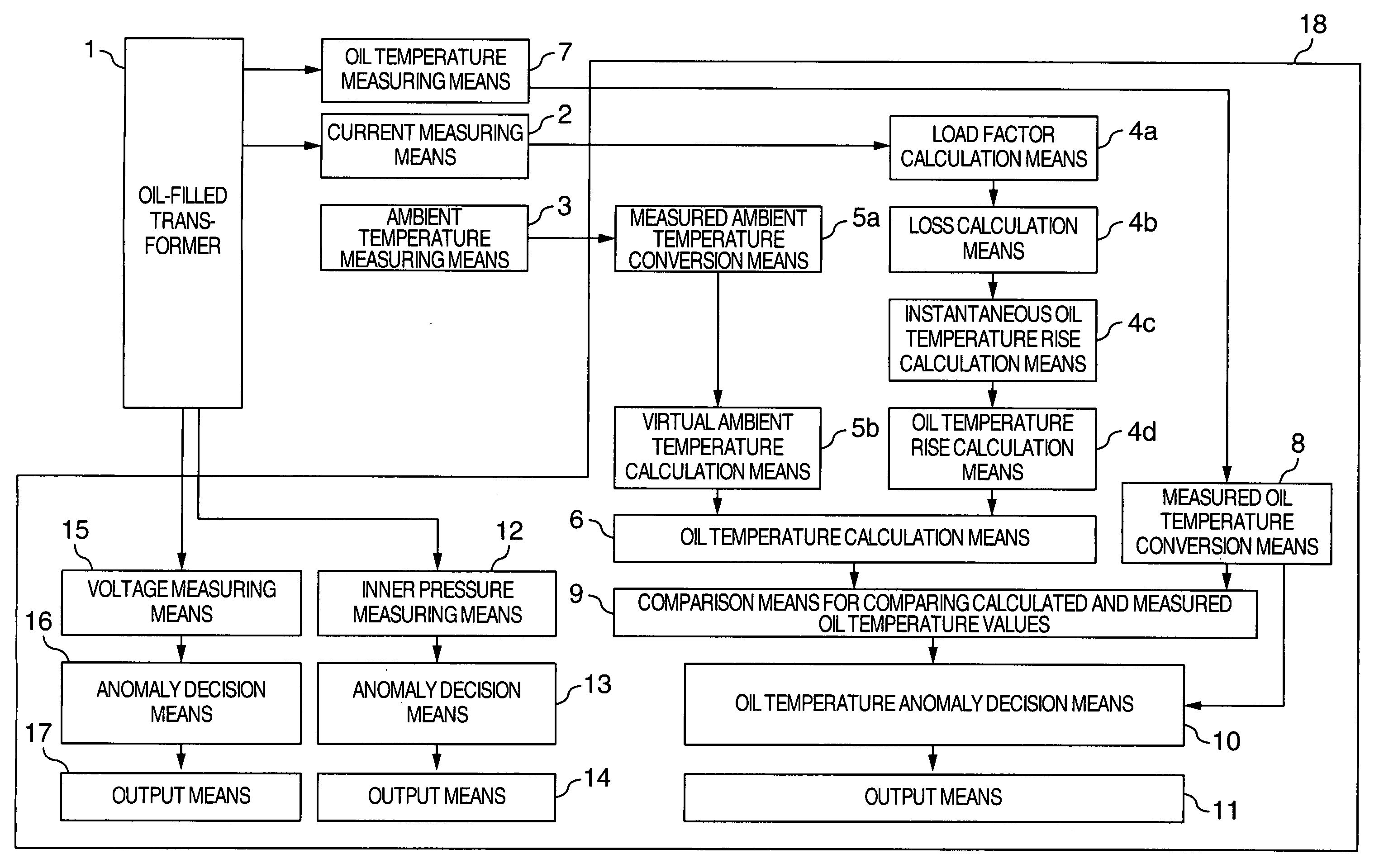
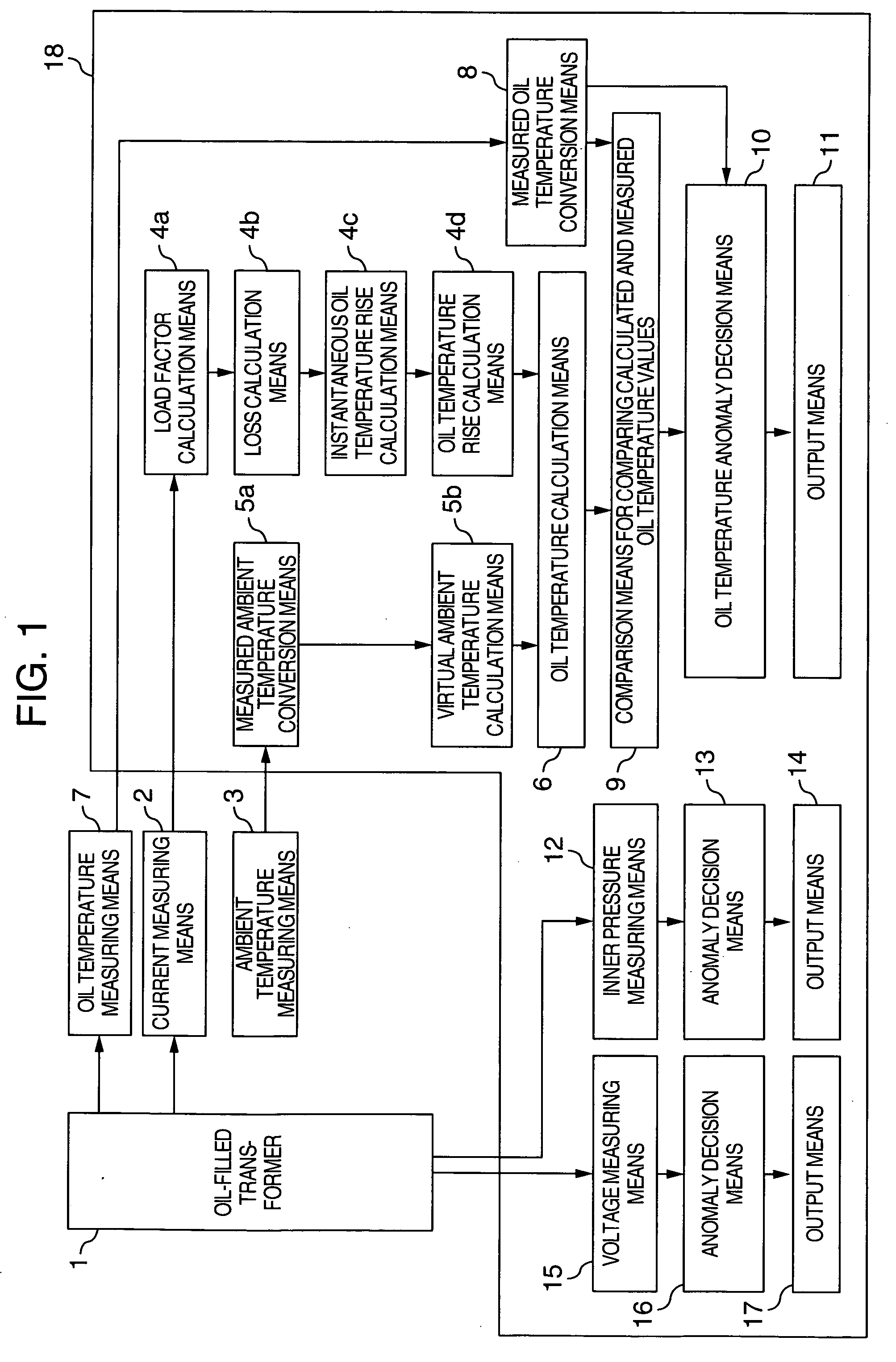
[0025]FIG. 1 is a block diagram of an oil-filled transformer monitoring system.

[0026] In FIG. 1, reference number 1 represents an oil-filled transformer; 2 a current measuring means constructed of a current transformer (CT) for metering current of the transformer; 3 an ambient temperature measuring means constructed of a temperature measuring resistor (search coil) for measuring an ambient temperature; 4a a load factor calculation means for calculating a load factor from a signal output from the current measuring means 2; 4b a loss calculation means for calculating a loss from a result produced by the load factor calculation means 4a; 4c an instantaneous oil temperature rise calculation means for calculating an instantaneous oil temperature...


PUM


Abstract

An oil-filled transformer monitoring system is provided which calculates an oil temperature of an oil-filled transformer with high precision from a current of the transformer and an ambient temperature. The oil-filled transformer monitoring system of this invention has an oil temperature calculation device to calculate a transformer oil temperature using measurements from a transformer current measuring device and an ambient temperature measuring device. The transformer monitoring system also has an oil temperature measuring device and compares an output value from the oil temperature calculation device with an output value from the oil temperature measuring device to detect any anomaly.

Description

INCORPORATION BY REFERENCE [0001] The present application claims priority from Japanese application JP 2004-112651 filed on Apr. 7, 2004, the content of which is hereby incorporated by reference into this application. BACKGROUND OF THE INVENTION [0002] The present invention relates to a monitoring of a state of oil-filled transformers using information such as transformer oil temperature, current and ambient temperature. [0003] A stable supply of electricity is important and it is therefore necessary to periodically monitor transformers to forestall possible failures. For this purpose, monitoring a voltage, current and oil temperature of the transformers is effective. The monitoring of the oil temperature generally involves estimating an oil temperature from an average load factor, visually checking a temperature reading on a thermometer, comparing the estimated oil temperature with the temperature reading on the thermometer to decide whether the transformer in question is normal or...

Claims


Application Information

Patent Timeline
IPC IPC(8): H01F27/00G01N11/00G01N33/28H02H7/04
CPCG01N33/28H01F2027/404
Inventor DOHI, MANABUSHIRAHATA, TOSHIKIKONDO, TAKAYUKI
Owner HITACHI IND EQUIP SYST CO LTD
Why Eureka
Try Eureka