Switch designation apparatus for a bicycle control unit

a technology of switch designation and control unit, which is applied in the direction of cycle equipment, transportation and packaging, gearing, etc., can solve the problems of troublesome and complex rewiring of the devi

Active Publication Date: 2005-10-13
SHIMANO INC
View PDF4 Cites 62 Cited by
  • Summary
  • Abstract
  • Description
  • Claims
  • Application Information

AI Technical Summary

Problems solved by technology

Rewiring the device would be very complex and troublesome.

Method used


Image

  • Switch designation apparatus for a bicycle control unit
  • Switch designation apparatus for a bicycle control unit
  • Switch designation apparatus for a bicycle control unit

Examples


Embodiment Construction

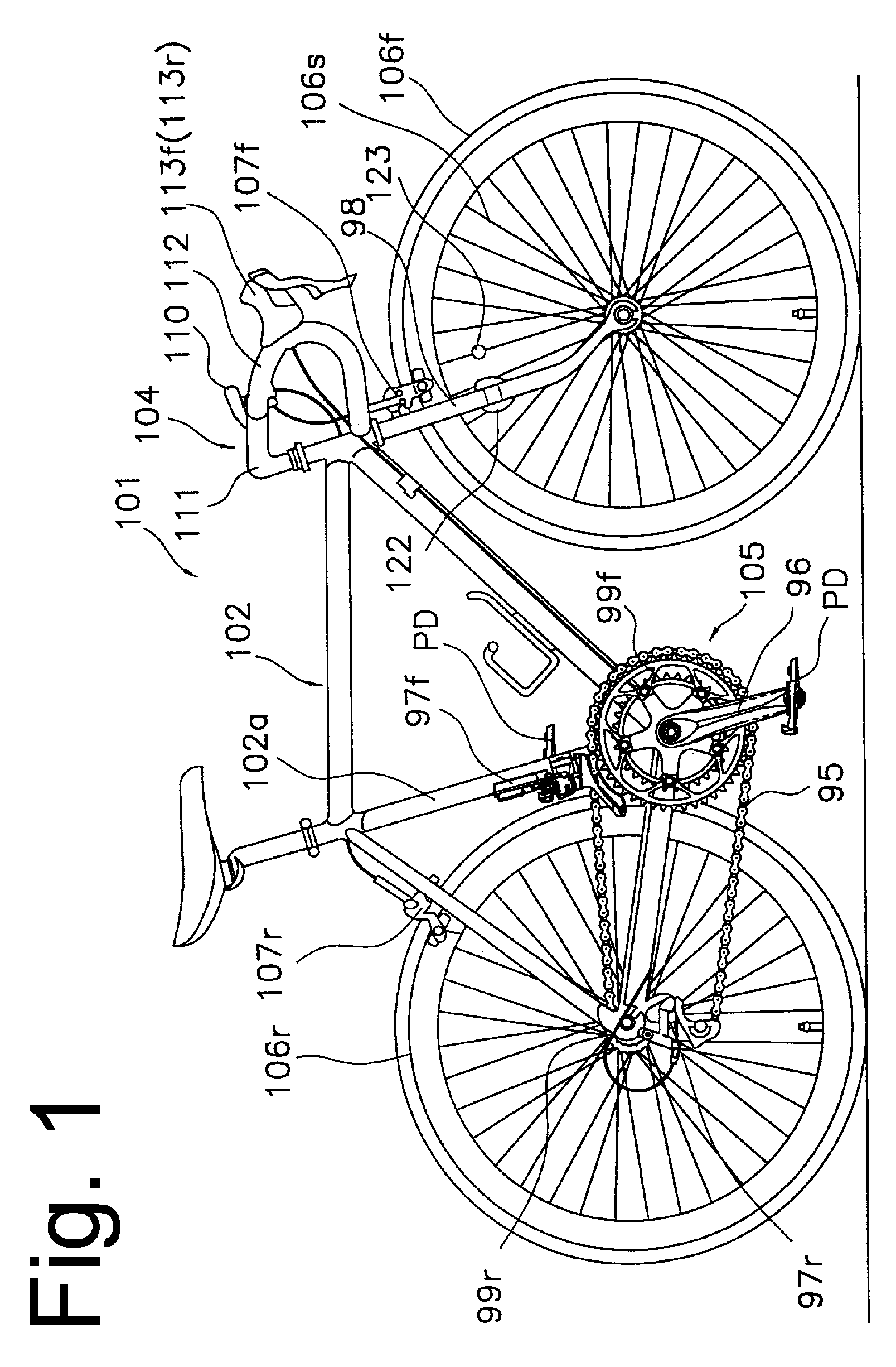
[0018]FIG. 1 is a side view of a bicycle 101 that includes particular embodiments of electrically controlled components. Bicycle 101 is a road bicycle comprising a diamond-shaped frame 102, a front fork 98 rotatably mounted to frame 102, a handlebar assembly 104 mounted to the upper part of fork 98, a front wheel 106f rotatably attached to the lower part of fork 98, a rear wheel 106r rotatably attached to the rear of frame 102, and a drive unit 105. A front wheel brake 107f is provided for braking front wheel 106f, and a rear wheel brake 107r is provided for braking rear wheel 106r.

[0019] Drive unit 105 comprises a chain 95, a front sprocket assembly 99f coaxially mounted with a crank 96 having pedals PD, an electrically controlled front derailleur 97f attached to a seat tube 102a of frame 102, a rear sprocket assembly 99r coaxially mounted with rear wheel 106r, and an electrically controlled rear derailleur 97r. As shown in FIG. 5, front sprocket assembly 99f comprises two coaxial...


PUM


Abstract

A switch designation apparatus for a bicycle control unit comprises a first switch structured to be mounted to a bicycle for providing signals to move a moving bicycle control device, a second switch structured to be mounted to the bicycle for providing signals to move the moving bicycle control device, and a switch designation unit that allows a user to selectively designate movements of the bicycle control device signaled by at least one of the first switch and the second switch.

Description

BACKGROUND OF THE INVENTION [0001] The present invention is directed to bicycles and, more particularly, to a switch designation apparatus for adjusting a position of a bicycle control unit. [0002] Bicycle transmissions that comprise front and rear derailleurs are well known. The front derailleur shifts a chain among a plurality of front sprockets that are coaxially mounted to the pedal crank shaft, and the rear derailleur shifts the chain among a plurality of rear sprockets that are coaxially mounted to the rear wheel. It is also known to use electric motors to operate the front and rear derailleurs. Such a system is shown in Japanese Kokai Patent Application No. 2001-267002. [0003] Bicycle transmissions formed inside the bicycle wheel hub (often called internal hub transmission) also are well known. Such transmissions include a planetary gear mechanism mounted inside the hub for communicating rotational force from a drive sprocket to the wheel hub shell through a plurality of tran...

Claims


Application Information

Patent Timeline
Patent Type & Authority Applications(United States)
IPC IPC(8): B62M25/08B62J99/00B62M11/16B62M9/12
CPCB62M25/08Y10T74/20438Y10T74/2003
Inventor TAKAMOTO, RYUICHIRO
Owner SHIMANO INC
Why Eureka
Try Eureka