Calibration camera device

Inactive Publication Date: 2005-10-13
GALLISTROFF SOFTWARE
View PDF1 Cites 7 Cited by
  • Summary
  • Abstract
  • Description
  • Claims
  • Application Information

AI Technical Summary

Benefits of technology

[0009] It is an object of the present invention to provide a not expensive calibration camera device with good operationality which is configured so

Problems solved by technology

At each projector, however, may occur geometrical distortion, color shading, luminance shading, difference in gamma characteristic, difference in white balance and the like.
In this case, the differences in image quality between the projectors become conspicuous, thereby deteriorating the displaying quality of the image displaying device.
Since the color measuring device is expensive and is required to be set at every point if in the color correction,

Method used


Image

  • Calibration camera device
  • Calibration camera device
  • Calibration camera device

Examples


Example

(First Embodiment)

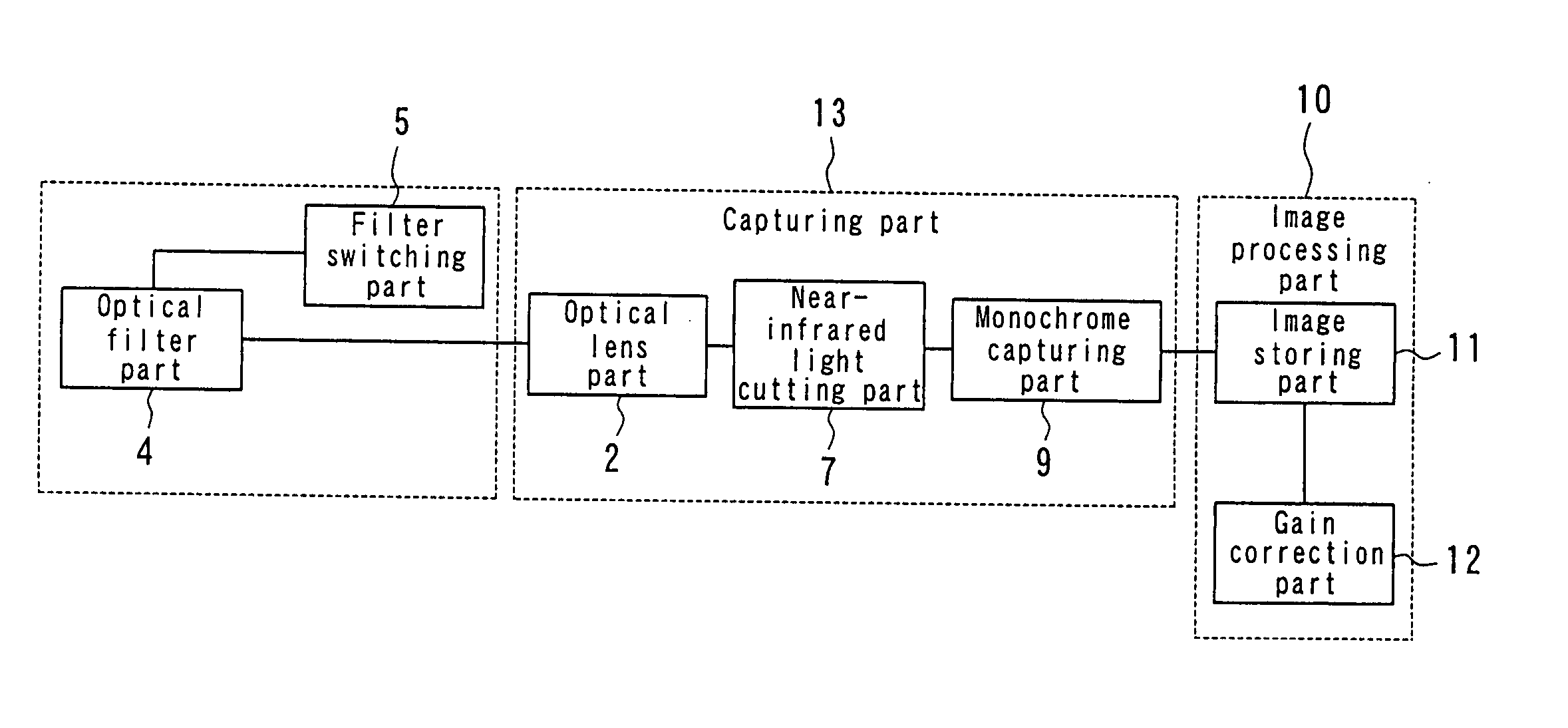
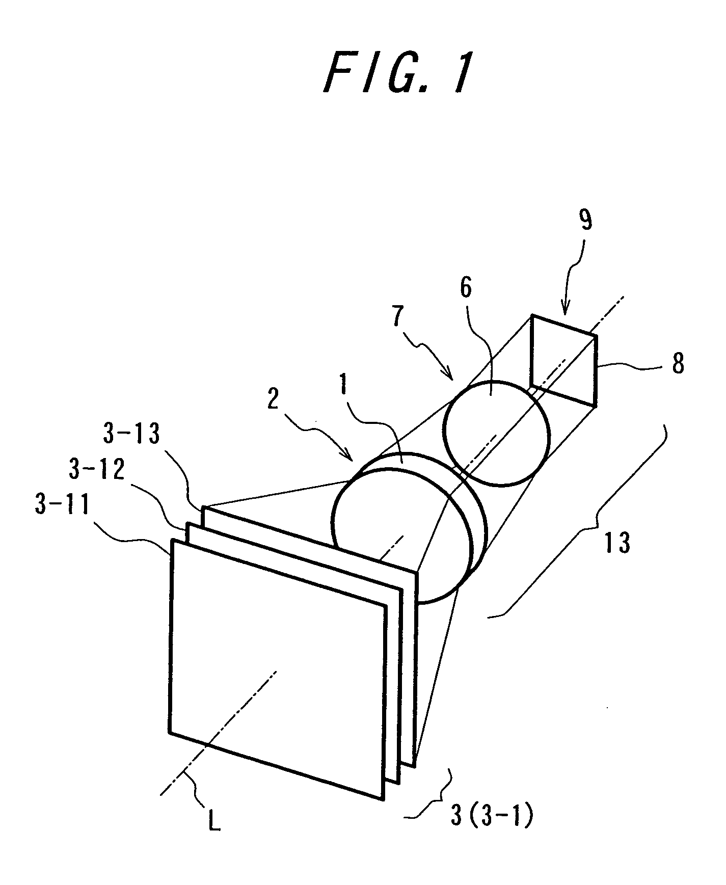
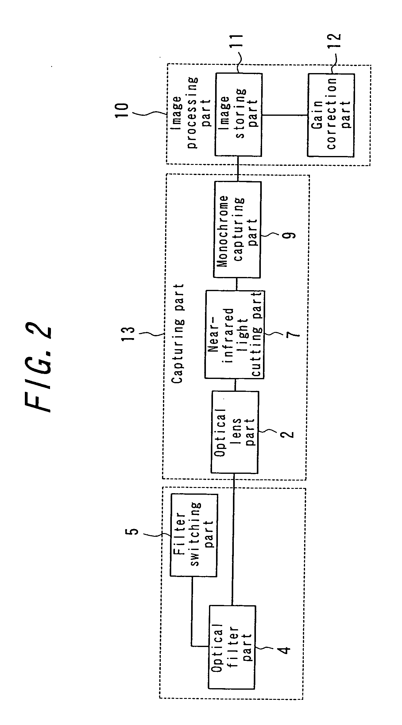
[0044]FIG. 1 is a perspective view showing the principal structure of a calibration camera device according to a first embodiment of the present invention. FIG. 2 is a functional block diagram of the calibration camera of the first embodiment. FIG. 3 is a top plan view of the calibration camera device of the first embodiment, as viewed from the top of the calibration camera device.

[0045] In this embodiment, the calibration camera is configured so that geometrical correction and color correction can be conducted simultaneously, and as shown in FIG. 1, includes an optical lens part 2 to which a lens 1 is attached, an optical filter part 4 which is located in front of the optical lens part 2 on the optical path L and to which at least three optical filters 3 are attached (in the embodiment shown in FIG. 3, three optical filters 3-1, 3-2, 3-3 are provided), a filter switching part 5 which selects one among the optical filters 3 which are attached to the optical filt...

Example

(Second Embodiment)

[0062]FIG. 6 is a view showing the substantial part of a calibration camera device according to a second embodiment of the present invention. In this embodiment, the calibration camera device includes a filter switching part 14 as shown in FIG. 6 which is diverted from a normal slide photograph equipment, instead of the rolling filter switching part 5. The filter switching part 14 is constituted from a frame member 14a with three or more openings 14b (in this embodiment, the number of the openings are set to six). Then, gelatine filters are attached to the openings, respectively, e.g., with adhesion as in the first embodiment. Each gelatine filter constitutes an optical filter. The optical filters is designated by reference numeral “3”, and each optical filter is numbered as 3-1, 3-2, 3-3 . . . . In the filter switching part 14, a desired filter can be positioned at the photometric point of the optical path by moving the frame member 14a back and forth as shown ...

Example

[Third Embodiment]

[0064] FIGS. 7(a) and (b) are characteristic views showing the spectral transmittance characteristics of a calibration camera device according to a third embodiment of the present invention. In this embodiment, the calibration camera device includes the color matching functions x(λ),y(λ),z(λ) of a three stimulus color XYZ displaying system as shown in FIG. 7(a), wherein the function x(λ) exhibits two peaks 15a and 15b. In this case, the function x(λ) can not be almost realized by selecting appropriate ones from among gelatine filters so as to constitute the optical filter so that the characteristic of the optical filter is similar to the characteristic of the function x(λ). In this point of view, it is preferred that the function x(λ) is realized by selecting appropriate ones from among gelatine filters so that the transmittance within the band range containing the smaller peak 15b is set to zero. In this case, the characteristic of the function x(λ) can be set al...


PUM


Abstract

A calibration camera device for geometrical correction or color correction, including an optical lens part, an optical filter part which is provided in front of the optical lens part and to which at least three optical filters are attached, a filter switching part to select any one from among the optical filters and dispose the selected one optical filter at a photometric point, a near-infrared light cutting part which is provided in the rear of the optical lens part and to which a near-infrared light cutting filter is attached, a monochrome capturing part which is provided in the rear of the near-infrared light cutting part and includes a monochrome imaging element, an image storing part for storing a monochrome image which is captured by the monochrome capturing part, and a gain correction part for conducting sensitivity correction on the monochrome image.

Description

BACKGROUND OF THE INVENTION [0001] 1. Field of the Invention [0002] The present invention relates to a calibration camera device which can be used in geometrical correction in combination with color correction by itself and particularly to a calibration camera device which is preferably used in image quality control of an image displaying device. [0003] 2. Description of the Related Art [0004] Conventionally, an image displaying device has been proposed wherein a plurality of images are projected from the corresponding projectors and synthesized as one large image on one screen. At each projector, however, may occur geometrical distortion, color shading, luminance shading, difference in gamma characteristic, difference in white balance and the like. In this case, the differences in image quality between the projectors become conspicuous, thereby deteriorating the displaying quality of the image displaying device. In this point of view, an image displaying device is proposed wherein ...

Claims


Application Information

Patent Timeline
IPC IPC(8): H04N17/02G01J3/51G01J3/50H04N5/232H01J40/14G03B11/00G03B15/00H04N9/04H04N17/00
CPCG01J3/0208G01J3/0235G01J3/465G01J3/51G03B11/00H04N9/3194
Inventor YAMAGUCHI, KAZUO
Owner GALLISTROFF SOFTWARE
Why Eureka
Try Eureka