Eureka AIR delivers breakthrough ideas for toughest innovation challenges, trusted by R&D personnel around the world.

Flush valve diaphragm orifice insert and rib design

Active Publication Date: 2005-10-13
ZURN INDS
View PDF36 Cites 8 Cited by
  • Summary
  • Abstract
  • Description
  • Claims
  • Application Information

AI Technical Summary

Benefits of technology

[0011] The present invention provides for a flush valve that includes a valve body having an inlet and an outlet, and a barrel section having a sealing end positioned within the valve body. The sealing end is defined between the inlet and the outlet, wherein the barrel section adapts to fluidly connect the inlet to the outlet. The flush valve also includes a diaphragm assembly as previously discussed positioned in the valve body and separating the inlet and the outlet. The diaphragm assembly is configured to have a pressure difference applied across the diaphragm assembly, wherein the second side of th

Problems solved by technology

Inadequate sealing of the diaphragm can occur when a diaphragm loses its elasticity and becomes distorted due to the constant flexing of the diaphragm after extensive use.
A clogged bypass orifice can prevent water from flowing to the top side of the diaphragm, which results in an inadequate seal.
In addition, water hammer resulting from the diaphragm closing too quickly against the valve body can also be a problem that affects the performance of the flush valve.

Method used


Image

  • Flush valve diaphragm orifice insert and rib design
  • Flush valve diaphragm orifice insert and rib design
  • Flush valve diaphragm orifice insert and rib design

Examples


Embodiment Construction

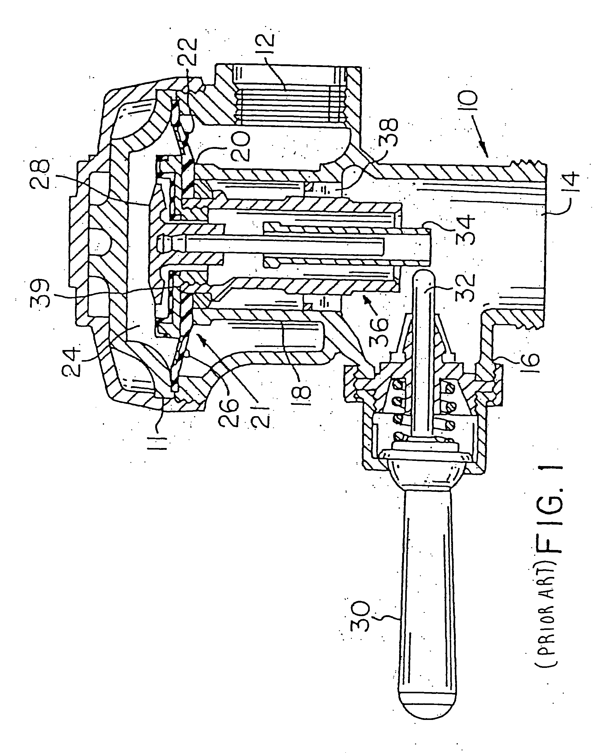
[0025] Flush valves in water closets, urinals, and other plumbing devices which utilize a flexible diaphragm to establish and to seal off the connection between the inlet and outlet are well known in the art. FIG. 1 illustrates a typical prior art flush valve and diaphragm assembly. The flush valve has a hollow valve body 10, generally made of brass, which includes an inlet 12, an outlet 14, and a handle connection 16. A barrel section 18 is positioned within the flush valve such that the connection between the inlet 12 and the outlet 14 is through the barrel section 18. An annular main valve seat 20 is formed on a top or sealing end 21 of the barrel section 18. The annular main valve seat 20 is normally closed by a diaphragm 22 extending across the body 10 and defining an upper chamber 24. The diaphragm 22 has a bypass 26 which provides fluid communication between the inlet 12 of the flush valve and the upper chamber 24. The diaphragm 22 is attached at its outer edge to the valve b...


PUM


Abstract

A diaphragm assembly for use in conventional diaphragm-type flush valves includes a flexible diaphragm body having a first side and a second side and a bypass orifice filter insert defined in the diaphragm body. The second side of the diaphragm body includes an annular protrusion and a plurality of protruding ribs, wherein a recess area is defined between the rib and the protrusion. When a pressure difference is applied across the diaphragm body, the second side of the diaphragm body is concave and the first side of the diaphragm body is convex, whereby a distance between the rib and the protrusion decreases in order to prevent the diaphragm body from closing two quickly against a valve seat of a flush valve. A method for controlling pressure differences across the diaphragm body is also disclosed.

Description

CROSS REFERENCE TO RELATED APPLICATION [0001] This application claims the benefit of U.S. Provisional Patent Application Ser. No. 60 / 394,472, filed Jul. 8, 2002, which is hereby incorporated by reference.BACKGROUND OF THE INVENTION [0002] 1. Field of the Invention [0003] The present invention relates, in general, to a flush valve diaphragm for urinals and other plumbing equipment and, more particularly, to a flush valve diaphragm rib design and bypass orifice filter insert. [0004] 2. Description of Related Art [0005] Typical diaphragm-type flush valves for use on toilet devices, such as urinals and water closets, utilize a flexible diaphragm to establish and to seal off the connection between an inlet and outlet of a flush valve. Typically, the diaphragm is made of an elastomeric material, such as rubber, and includes a filter and a bypass orifice which provides fluid communication between the inlet side of the flush valve and an upper chamber of the flush valve. Such flush valve di...

Claims


Application Information

Patent Timeline
IPC IPC(8): E03D3/06
CPCE03D3/06Y10T137/8122
Inventor FUNARI, MICHAEL A.O'CONNOR, J. TIMOTHY
Owner ZURN INDS
Why Eureka
Eureka Blog
Learn More