Gas generator

a generator and gas technology, applied in the direction of separation process, pedestrian/occupant safety arrangement, filtration separation, etc., can solve the problems of reducing the size of the airbag module, and requiring a large amount of generated gas

Inactive Publication Date: 2005-10-13
NIPPON KAYAKU CO LTD
View PDF32 Cites 36 Cited by
  • Summary
  • Abstract
  • Description
  • Claims
  • Application Information

AI Technical Summary

Benefits of technology

[0011] This construction can provide the result that even when the gas generator is reduced in number of components and is simplified in structure, deformation of the housing can be suppressed even when the pressure in the housing is increased by the gas generated by burning the gas generant in the combustion chamber. This can provide a reduced number of components and a simplified structure, thus enabling reduction in size and weight of the gas generator and a significant reduction of manufacturing cost.
[0051] In addition, since there is no need to cover the entire gas generator, as the airbag module using the conventional passenger's seat gas generator does, the structure of the gas generator holding portion of the airbag module can also be simplified.

Problems solved by technology

However, this double-cylinder type gas generator requires an increased number of components of the gas generator and also requires a complicated structure, as shown in FIG. 8.
Due to this, there are limits for this type of gas generator to cut the production cost while maintaining the safety of the gas generator.
Further, this type of gas generator has a small capacity to hold the gas generant.
Due to this, it is mainly applied to a driver's side airbag system and is never applicable to a passenger's seat airbag system requiring a large amount of generated gas.
Also, the way of and the structure for assembling the gas generator in the airbag module are complicated, thus involving troublesome works.
Also, owing to the cylindrical shape, it is difficult to pack the gas generant 86 in the interior of the housing with high packing efficiency.

Method used


Image

  • Gas generator
  • Gas generator
  • Gas generator

Examples


examples

[0125] In the following, the gas generator according to the present invention is described with reference to Examples.

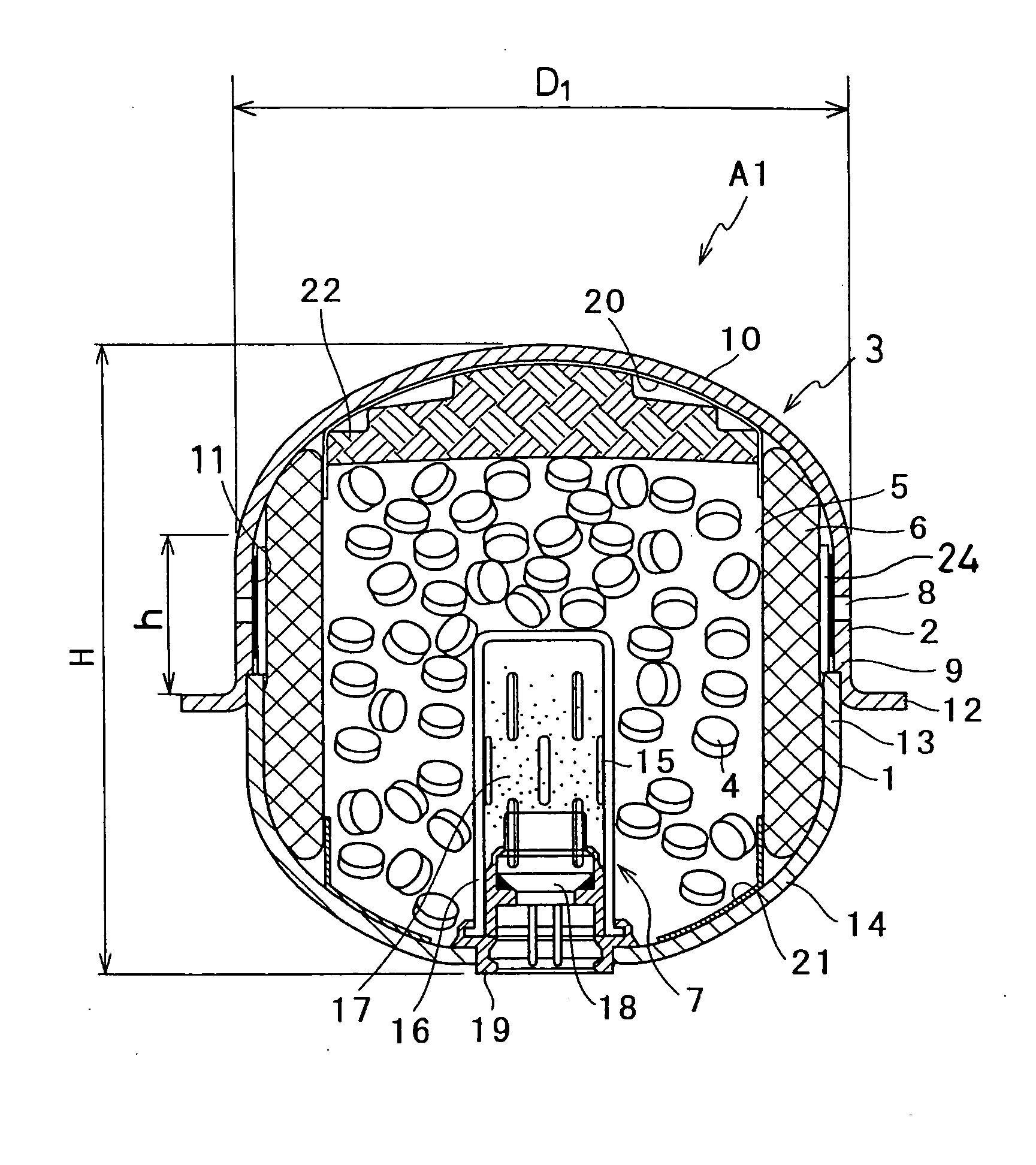
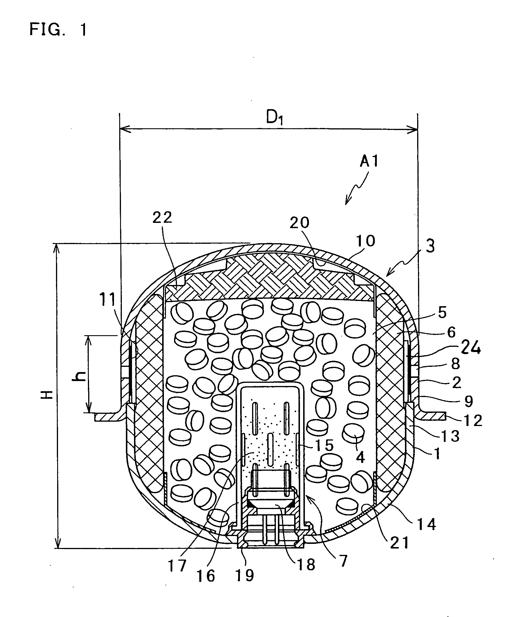
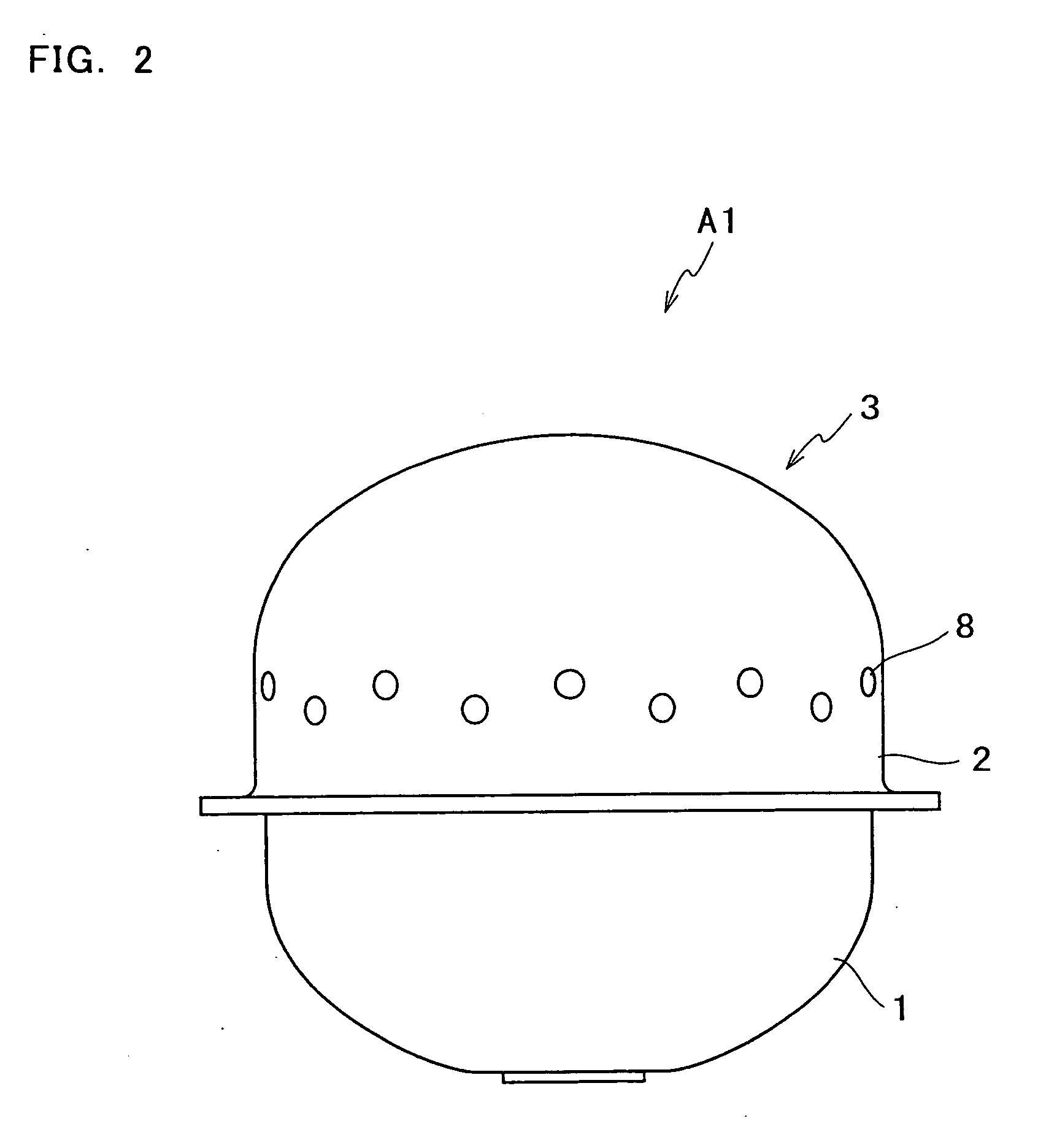
[0126] In the gas generator shown in FIGS. 1 and 2, a stainless material having a thickness of 2 mm was pressed to form the closure shell having the following dimensions: 75 mm in distance H between the bottoms of the head portions 10, 14; 70 mm in diameter D1 of the cylindrical portion 9; 16 mm in h; 70 mm in major axis d2 of the head portion 10 of the closure shell 2; 45 mm in minor axis d1 of the same; and 45 mm in curvature radius R of the head portion on the closure shell side. Also, a stainless material having a thickness of 2 mm was pressed to form the initiator shell 1 having the following dimensions: 67 mm in major axis d2 of the head portion 14; 42 mm in minor axis d1 of the same; and 20 mm in curvature radius r of the head portion on the initiator shell side. Then, the igniter device 7 and the filter member 6 were placed in sequence in the initiator shell...


PUM

PropertyMeasurementUnit
heightaaaaaaaaaa
heightaaaaaaaaaa
heightaaaaaaaaaa

Abstract

A gas generator comprising a housing (3) made of metal and having an initiator shell (1) and a closure shell (2), (a) combustion chamber(s) (5, 5a, 5b) formed in the housing (3) and packed with gas generant (4) that generates high temperature gas by burning, (a) filter member(s) (6, 6a, 6b) arranged around the combustion chamber(s) (5, 5a, 5b), (an) igniter device(s) (7, 7a, 7b) put in the housing (3) for igniting and burning the gas generant (4) in the combustion chamber(s) (5, 5a, 5b), and a plurality of gas discharge holes (8) formed at the housing (3), for discharging gas generated in the combustion chamber(s) (5, 5a, 5b), wherein either or both of the initiator shell (1) and the closure shell (2) forming the housing (3) has a head portion (14, 10) of a semispherical form or an oval semispherical form and a cylindrical portion (13, 9) of a diameter (D) formed continuously from the head portion (14, 10), and wherein a ratio H / D between the diameter D of the cylindrical portion (13, 9) and a distance H between bottoms of the head portions (14, 10) of the initiator shell (1) and closure shell (2) is in the range of 0.4-1.3.

Description

TECHNICAL FIELD [0001] The present invention relates to a gas generator suitably used to expand an airbag and the like. BACKGROUND ART [0002] A gas generator used to expand and inflate the airbag rapidly so as to protect a vehicle occupant from the shock at a car collision is built in an airbag module secured in a steering wheel or an instrument panel. The gas generator operates to ignite an igniter device (squib) under control of electrical signals from a control unit (controller) to burn enhancer agent (enhancer) and then burn gas generant by the flames of the enhancer agent, thereby generating a large amount of gas rapidly. [0003] A so-called, double-cylinder type gas generator having a central space, equivalent to an ignition chamber of the gas generant, and an annular space, equivalent to a combustion / filtering chamber, formed at the outside of the central space concentrically, for burning and cooling gas and collecting slag is known as a conventional gas generator. [0004] This...

Claims


Application Information

Patent Timeline
Patent Type & Authority Applications(United States)
IPC IPC(8): B60R21/20B60R21/272B60R21/26B60R21/263B60R21/264C06D5/06
CPCB60R21/2644B60R2021/2633B60R2021/2648C06D5/06B60R21/272B60R21/20B60R21/26
Inventor SUEHIRO, AKIHIKODOSAI, TAKAYOSHISAITO, TETSUOKAWAKAMI, TAMEOSATO, EISHI
Owner NIPPON KAYAKU CO LTD
Why Eureka
Try Eureka