Liquid crystal display device

a liquid crystal display and display panel technology, applied in the direction of identification means, electrical apparatus casings/cabinets/drawers, instruments, etc., can solve the problems of plurality of liquid crystal display panels, troublesome parts management, increase production costs, etc., and achieve easy machined, easy to fix, excellent workability

Inactive Publication Date: 2005-10-13
ORION ELECTRIC CO LTD
View PDF3 Cites 6 Cited by
  • Summary
  • Abstract
  • Description
  • Claims
  • Application Information

AI Technical Summary

Benefits of technology

[0016] According to the structure according to the fourth aspect of the invention, when the cylindrical member is fixed by being swaged to the hole in the flat plate, since the cylindrical member is a brass member, which can be easily machined, the cylindrical member can be easily fixed to the hole, which provides excellent workability and improves productivity.
[0017] The liquid crystal display device according to the first aspect of the invention is the liquid crystal display device which fixes any one liquid crystal display panel selected from a plurality of liquid crystal display panels to a mounting cover fixed to the inner side of a cabinet, comprising amounting section capable of mounting the plurality of liquid crystal display panels onto the mounting cover, characterized in that the plurality of liquid crystal display panels of different mounting specifications are constructed so as to be fixed by the common mounting cover, and any of the different liquid crystal display panels can be fixed to the mounting cover, which provides excellent versatility and can also reduce the number of parts and thereby facilitates parts control and also provides excellent cost effectiveness.
[0018] The liquid crystal display device according to the second aspect of the invention is the liquid crystal display device according to the first aspect of the invention, characterized in that the plurality of liquid crystal display panels comprise a first liquid crystal display panel, a second liquid crystal display panel, and a third liquid crystal display panel having substantially the same outer shape and differing from one another in thickness, when the first liquid crystal display panel is attached to the mounting cover, a protruding folded lug is provided on one side of the first liquid crystal display panel, a mounting piece contacting the folded lug in which a first screw hole is formed in the mounting cover by being folded as a piece integral therewith, a fixing screw is passed through a first insertion hole provided in this folded lug so as to be screwed into the first screw hole, when the second liquid crystal display panel instead of the first liquid crystal display panel is attached to the mounting cover, a fixing screw is passed through a second insertion hole formed at one end of the mounting cover, screwed into a second screw hole provided on one side of the second liquid crystal display panel, and when the third liquid crystal display panel instead of the first liquid crystal display panel or the second liquid crystal display panel is attached to the mounting cover, one end of a hollow cylindrical member is attached to a flat plate of the mounting cover, the cylindrical member is passed through a mounting hole provided in the third liquid crystal display panel and fixed to the third liquid crystal display panel by screwing a fixing screw into a third screw hole formed inside the cylindrical member, which allows the first liquid crystal display panel, the second liquid crystal display panel, and third liquid crystal display panel differing from one another in thickness to be selected and attached to a common mounting cover, and thereby eliminates the necessity to provide mounting covers corresponding to the respective liquid crystal display panels, which provides excellent versatility and at the same time makes it possible to save the die manufacturing cost and remodeling cost, reduce the number of parts, facilitate parts control and provide excellent mounting workability.
[0019] The liquid crystal display device according to the third aspect of the invention is the liquid crystal display device according to the second aspect of the invention, characterized in that the material of the cylindrical member is brass and brass which is an alloy of copper and zinc has a yellow color, which provides excellent visibility and allows smooth mounting work and improves workability. Furthermore, using brass as the material of the cylindrical member improves rust-proofing characteristics and provides excellent durability.
[0020] The liquid crystal display device according to the fourth aspect of the invention is the liquid crystal display device according to the second or the third aspect of the invention, characterized in that one end of the cylindrical member is fixed by being swaged to a hole formed in the flat plate, and when the cylindrical member is fixed by being swaged to the hole in the flat plate, since the cylindrical member is a brass member which can be easily machined, the cylindrical member can be easily fixed to the hole, which facilitates the fixing of the cylindrical member to the hole and improves productivity.

Problems solved by technology

However, the structure as described in Patent Document 1 that a plurality of LCDs of different mounting specifications are fixed to a common cabinet using LCD screw holes and a plurality of types of fittings corresponding to the mounting section formed in the cabinet requires special-purpose fittings for different LCDs, which not only causes an increase in production costs but also requires troublesome parts management as the number of parts increases.
However, the liquid crystal display panel mounting structures disclosed in the aforementioned Patent Document 1 and Patent Document 2 do not allow the plurality of liquid crystal display panels to be fixed to a common mounting cover.

Method used


Image

  • Liquid crystal display device
  • Liquid crystal display device
  • Liquid crystal display device

Examples


Embodiment Construction

[0031] With reference now to FIGS. 1 to 10, one preferred embodiment of implementing the present invention will be explained below.

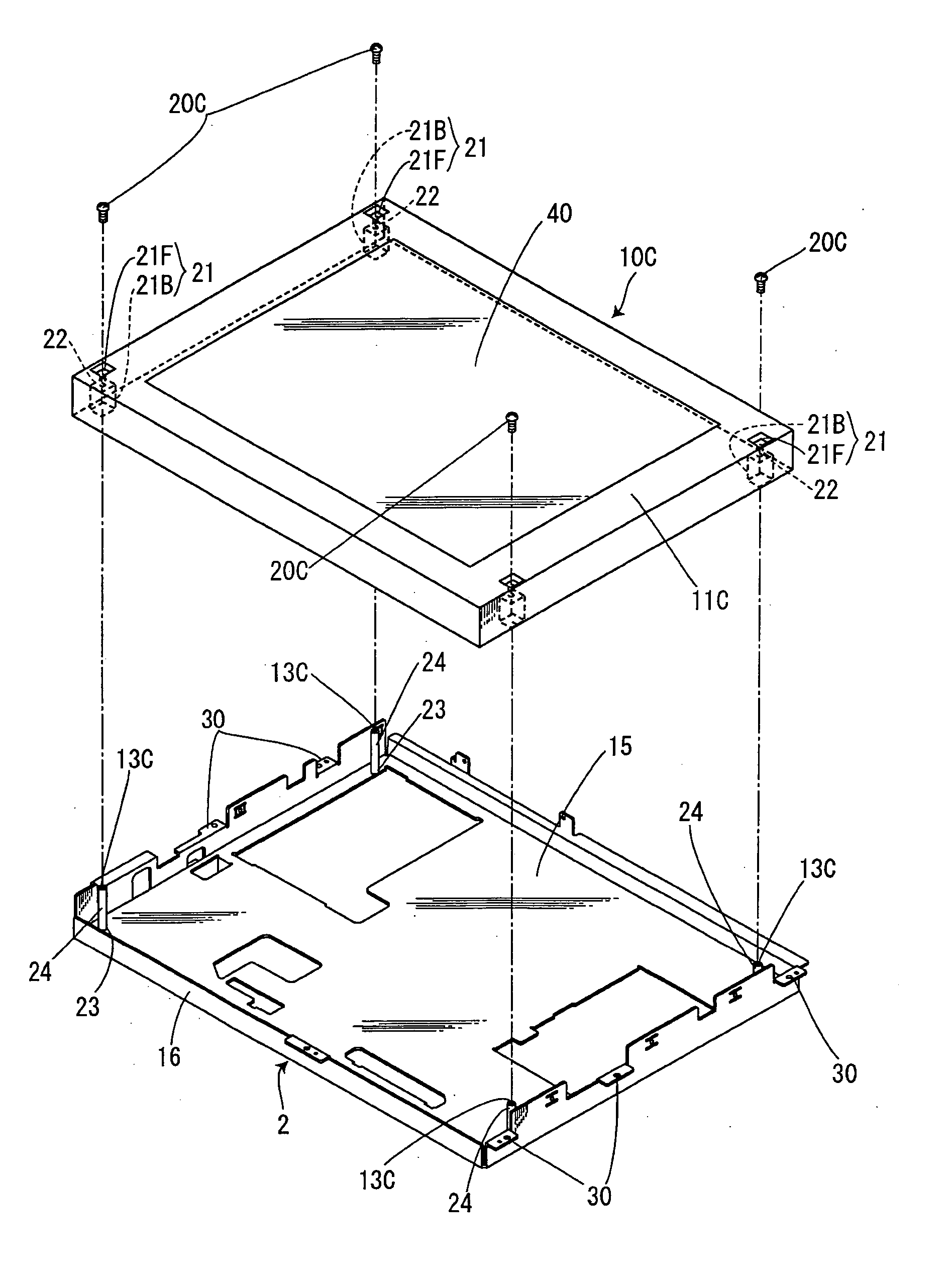
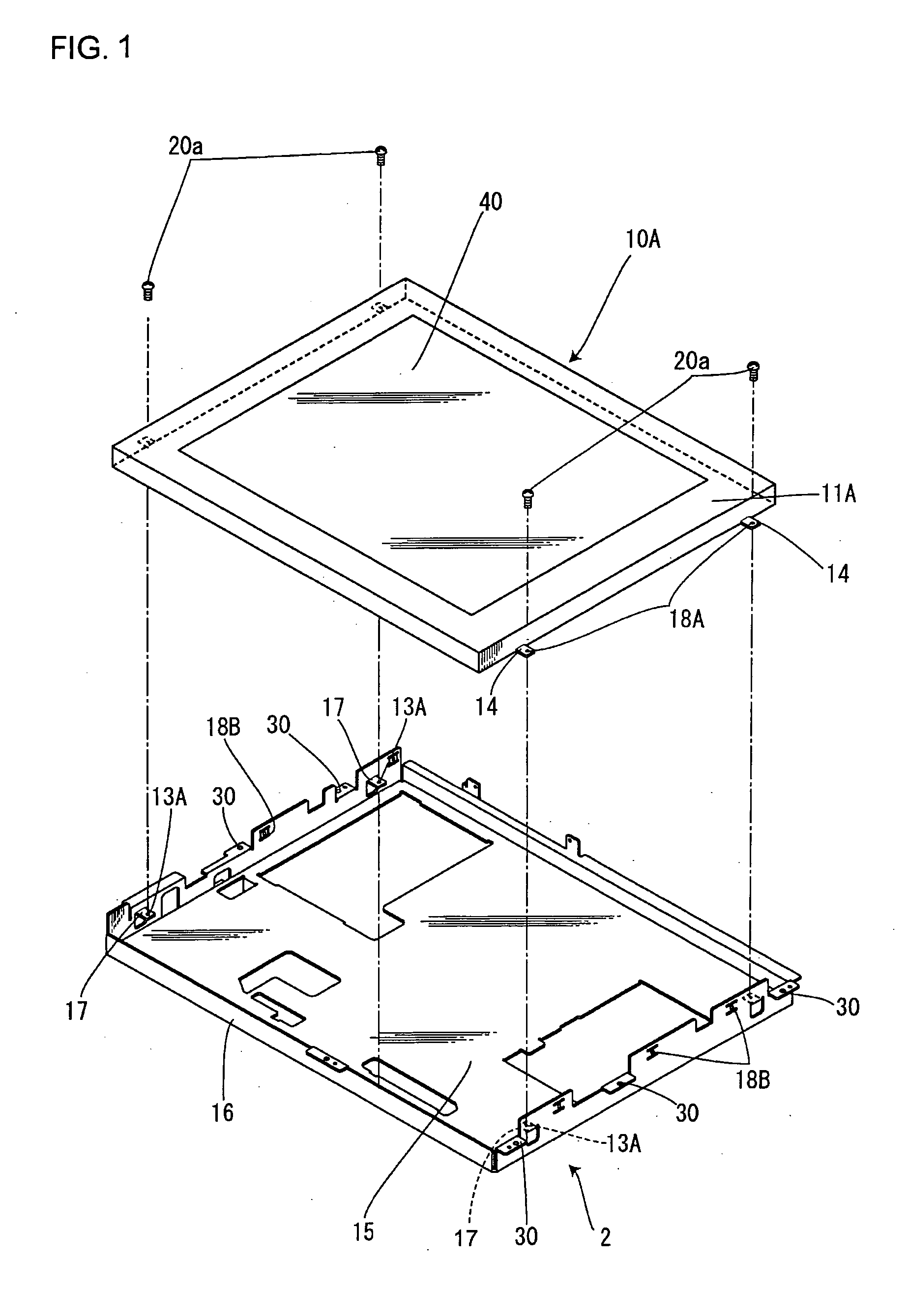
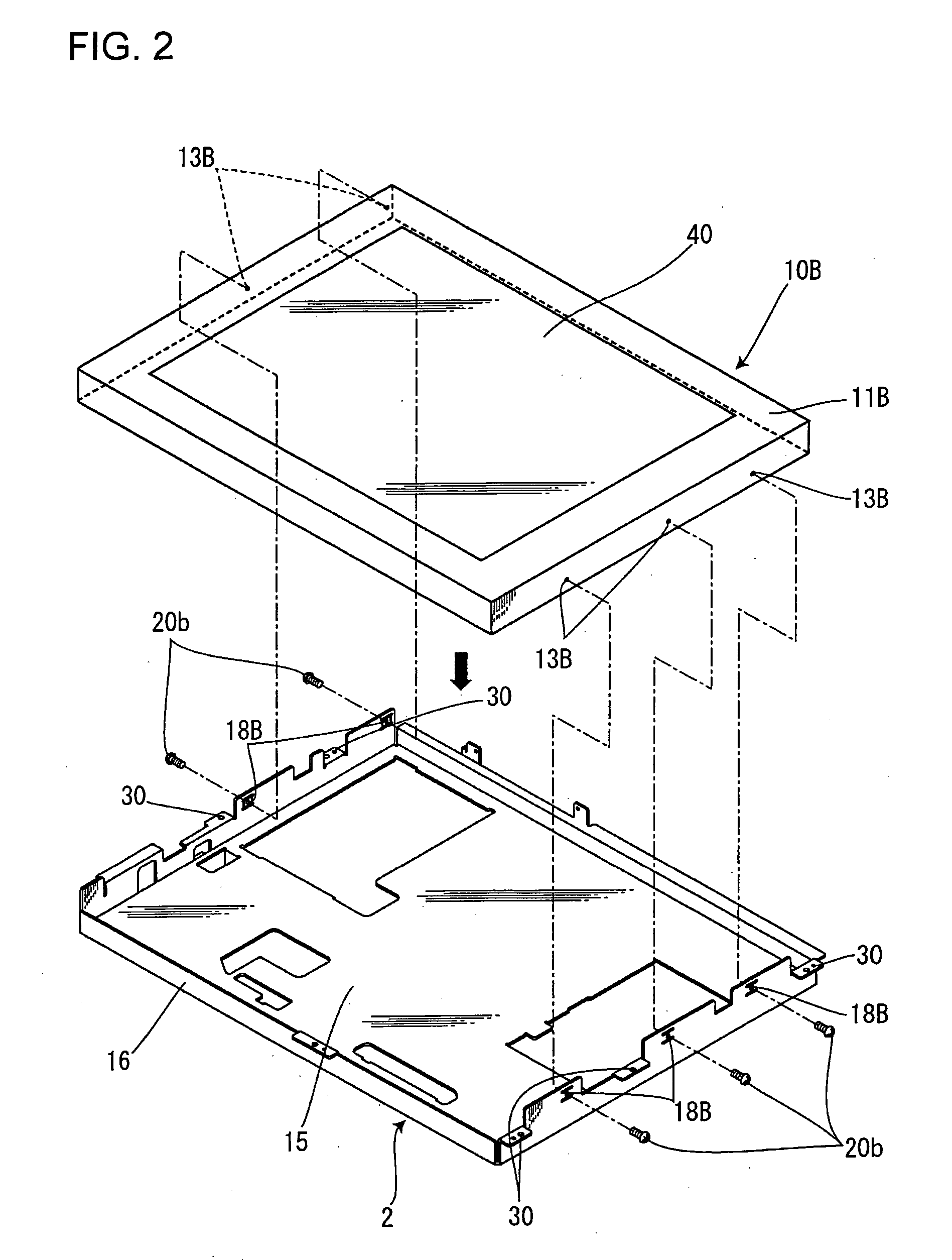
[0032]FIG. 1 is an exploded perspective view of a first liquid crystal display panel and a mounting cover, FIG. 2 is an exploded perspective view of a second liquid crystal display panel and a mounting cover, and FIG. 3 is an exploded perspective view of a third liquid crystal display panel and a mounting cover.

[0033] Reference number 1 denotes a liquid crystal panel unit of the present invention and this liquid crystal panel unit 1 is constructed of three types of a first liquid crystal display panel 10A, a second liquid crystal display panel 10B, and a third liquid crystal display panel 10C of different mounting specifications, a mounting cover 2 for fixing these liquid crystal display panels to a cabinet which will be described later and a circuit substrate (not shown) fixed to this mounting cover 2 and the like.

[0034] The first, the second, and th...


PUM

PropertyMeasurementUnit
thicknessaaaaaaaaaa
strengthaaaaaaaaaa
workabilityaaaaaaaaaa

Abstract

The invention provides a liquid crystal display device which allow a plurality of liquid crystal display panels of different mounting specifications to be fixed using a common mounting cover.
Mounting sections such as screw holes 13A, 13B, and 13C are provided to allow different first, second, and third liquid crystal display panels 10A, 10B, and 10C to be attached to a mounting cover 2. It is possible to fix the first, the second, or the third liquid crystal display panel 10A, 10B, or 10C of different mounting specifications to a common mounting cover 4, fix any one of different liquid crystal display panels to the mounting cover 2, provide excellent versatility, reduce the number of parts and thereby facilitate parts control and provide excellent cost efficiency.

Description

[0001] The present application is based on and claims priority of Japanese patent application No. 2004-115877 filed on Apr. 9, 2004, the entire contents of which are hereby incorporated by reference. BACKGROUND OF THE INVENTION [0002] 1. Field of the Invention [0003] The present invention relates to a liquid crystal display device designed to fix a plurality of liquid crystal display panels of different mounting specifications to amounting cabinet using a common mounting cover. [0004] 2. Description of the Related Art [0005] In recent years, a liquid crystal display panel is used as a display screen for a notebook or a desktop personal computer or a television device. For this type of liquid crystal display device, it is often the case that a multiple types of LCD manufactured by a plurality of manufacturers are mounted in a single cabinet. As a method of mounting such multiple types of LCD in one type of cabinet, for example, Japanese Patent Laid-Open Publication No. 2001-834.86 (P...

Claims


Application Information

Patent Timeline
Patent Type & Authority Applications(United States)
IPC IPC(8): G02F1/13G09F9/00G02F1/1333H05K5/00
CPCG02F2201/46G02F1/133308
Inventor AKAGAWA, KOUJINISHIDA, KAZUFUMIYONEZU, YOSHIKAZU
Owner ORION ELECTRIC CO LTD
Why Eureka
Try Eureka