Loop avoidance for recovery paths in mesh networks

a mesh network and recovery path technology, applied in the field of communication networks, can solve the problems of inefficient use of network bandwidth, expensive overbuilding of capacity, and current link-based recovery solutions that fail to adequately address loops in recovery paths

Inactive Publication Date: 2005-10-13
LUCENT TECH INC
View PDF84 Cites 10 Cited by
  • Summary
  • Abstract
  • Description
  • Claims
  • Application Information

AI Technical Summary

Benefits of technology

[0013] One or more embodiments of the present invention may provide the ability to calculate recovery paths taking into account protected segments that include shared risk link groups. One or more embodiments of the present invention may provide the ability to take advantage of information that can be calculated and/or d

Problems solved by technology

We have recognized that current solutions for link-based recovery fail to adequately address loops in recovery paths.
To some extent, this is a result of a lack of availability of information related to sharing and link state a

Method used


Image

  • Loop avoidance for recovery paths in mesh networks
  • Loop avoidance for recovery paths in mesh networks
  • Loop avoidance for recovery paths in mesh networks

Examples


Embodiment Construction

[0027] Reference herein to “one embodiment” or “an embodiment” means that a particular feature, structure, or characteristic described in connection with the embodiment can be included in at least one embodiment of the invention. The appearances of the phrase “in one embodiment” in various places in the specification are not necessarily all referring to the same embodiment, nor are separate or alternative embodiments mutually exclusive of other embodiments.

[0028] Introduction

[0029] Link-based recovery as implemented in the prior art suffers from a number of limitations including inefficient use of bandwidth, backhaul, and a failure to fully address bandwidth-sharing opportunities and recovery management at a granularity that is below the link / port (e.g., wavelength) level.

[0030] Recovery Granularity

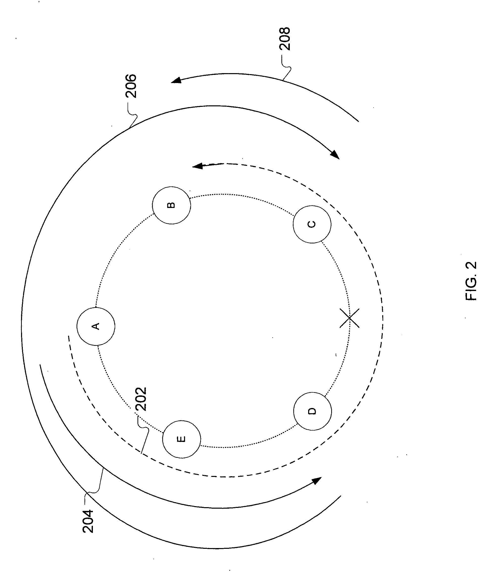
[0031] In optical ring networks of the prior art, the granularity with which link-based protection is implemented is too coarse (e.g., link or line level). Link-based protection of th...


PUM


Abstract

A protected communication network utilizes a link-based recovery strategy that incorporates loop-avoidance mechanisms to eliminate redundant traversal of links in recovery paths, thereby improving network efficiency. The loop-avoidance mechanisms can include calculation of recovery paths taking into account protected segments that include shared risk link groups. In one two-phase loop-avoidance mechanism, a full link-detour path is calculated for a primary-path link by generating a minimum cost path between the upstream and downstream terminating nodes for the link. Next, the full link-detour path is shortened by removing redundant links that are shared by the full link-detour path and the original primary path. Calculation of link-detours and elimination of loops is supported in some embodiments by the distribution of link-state parameters via extensions to the link-state-advertisement (LSA) protocol.

Description

CROSS-REFERENCE TO RELATED APPLICATIONS [0001] The subject matter of this application is related to U.S. patent application Ser. No. 10 / 639,728 filed on Aug. 12, 2003 as attorney docket no. Dziong 8-25-16-32; application Ser. No. 10 / 673,381 filed on Sep. 26, 2003 as attorney docket no. Doshi 56-5-21-17-33; application Ser. No. 10 / 673,383 filed on Sep. 26, 2003 as attorney docket Ser. No. Doshi 57-6-22-18-34; application Ser. No. 10 / 673,382 filed on Sep. 26, 2003 as attorney docket no. Doshi 55-7-23-15-35; application Ser. No. 10 / 673,056 filed on Sep. 26, 2003 as attorney docket no. Alfakih 1-1-1-6-24; application Ser. No. 10 / 673,057 filed on Sep. 26, 2003 as attorney docket no. Dziong 9-1; and application Ser. No. 10 / 673,055 filed on Sep. 26, 2003 as attorney docket no. Doshi 58-10-27-19-36, the teachings of all of which are incorporated herein by reference. [0002] This application is one of a set of U.S. patent applications consisting of application no. 10 / ______ filed as attorney ...

Claims


Application Information

Patent Timeline
IPC IPC(8): H04L12/28H04L12/43H04L12/46
CPCH04L12/4637H04L12/43
Inventor DZIONG, ZBIGNIEW M.QURESHI, MUHAMMAD A.WANG, YUNG-TERNG
Owner LUCENT TECH INC
Why Eureka
Try Eureka