Phase based feedback oscillation prevention in hearing aids

a phase-based feedback and hearing aid technology, applied in the direction of deaf-aid sets, electrical devices, etc., can solve the problems of difficult control of feedback oscillation, unpleasant noise or whistle produced by the user and others in close proximity, and the frequency of feedback oscillation is often subject to feedback oscillation, so as to prevent the oscillation of feedback signals without limiting the power of the hearing aid. , to achieve the effect of improving hearing quality

Inactive Publication Date: 2005-10-13
COCHLEAR LIMITED
View PDF17 Cites 57 Cited by
  • Summary
  • Abstract
  • Description
  • Claims
  • Application Information

AI Technical Summary

Benefits of technology

[0007] In view of the foregoing, a primary object of the present invention is to improve hearing quality for hearing aid users, referred to herein as patients. Another object of the present invention is to proactively compensate, rather than reactively compensate, for oscillation of feedback signals in hearing aids, including entirely and / or partially implantable hearing aids as well as conventional hearing aids. Another object of the present invention is to prevent oscillation of feedback signals without limiting the power of the hearing aid.

Problems solved by technology

Unfortunately, hearing aid devices, such as those described above, are often subject to feedback oscillation, e.g. resonant phenomenon due to re-amplification of feedback signals having a net phase of zero degrees.
When feedback signals, audible or not, oscillate through the hearing aid, they produce an unpleasant noise or whistle detectable by the user and others in close proximity.
Unfortunately, however, feedback oscillation is difficult to control because of the close proximity between the microphone and other components of the hearing aid, e.g. the amplifier.
This technique, however, suffers from the disadvantage of limiting the actual output power available for the hearing aid.
In addition, it can also decrease the ability of the patient to clearly understand speech, especially when background noise is present, and / or the speech includes an accent.
The disadvantage of these techniques, however, is that they address the problem of feedback through reactive compensational responses, which helps, but does not solve the problem.
A further disadvantage is a comparatively high cost of digital processing.

Method used


Image

  • Phase based feedback oscillation prevention in hearing aids
  • Phase based feedback oscillation prevention in hearing aids
  • Phase based feedback oscillation prevention in hearing aids

Examples


first embodiment

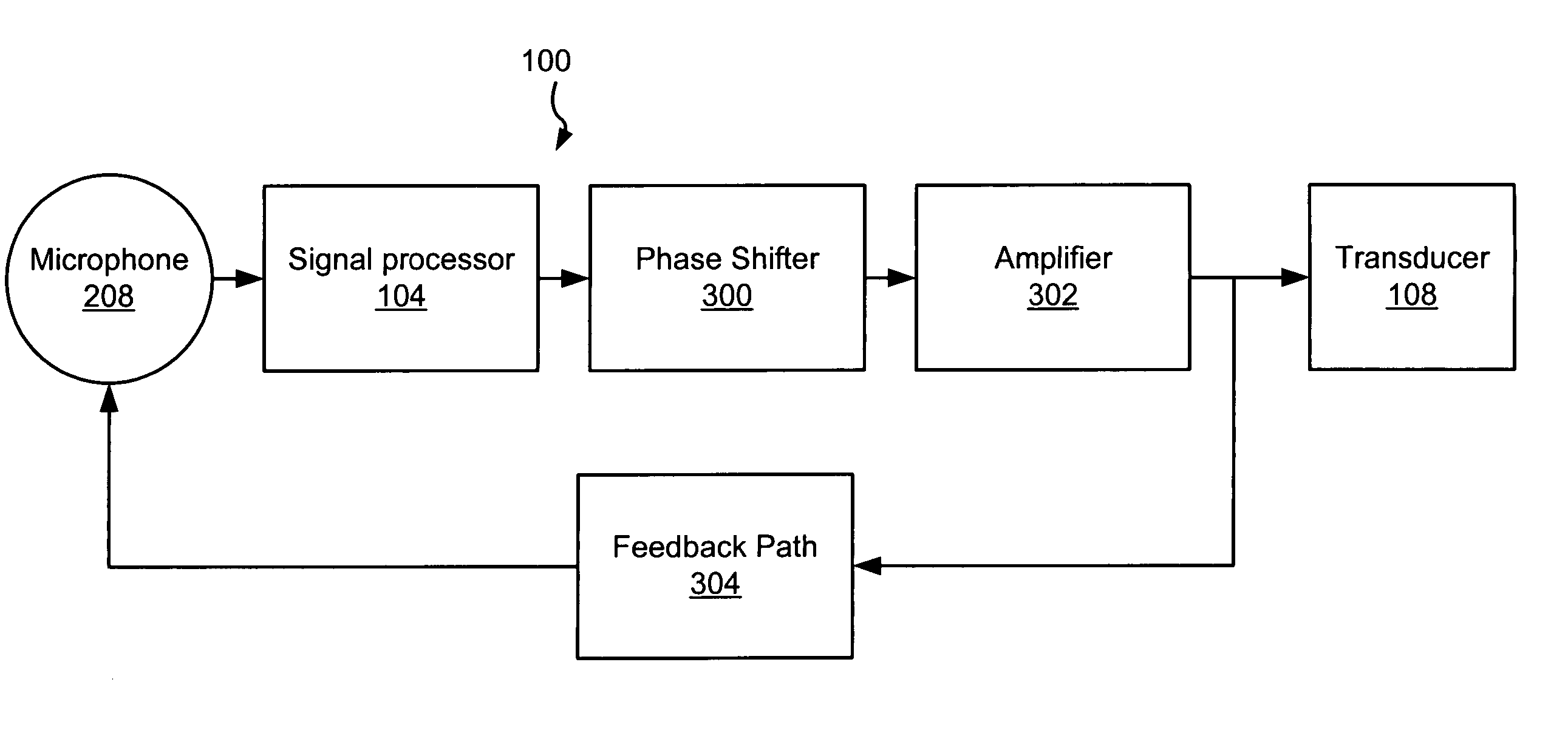
[0037]FIG. 3 illustrates a partial schematic representation of the hearing aid device 100 configured according to the present invention. According to this embodiment, the hearing aid device 100 includes the microphone 208, the signal processor 104, the transducer 108, an amplifier 302, and a phase shifter 300. It will be appreciated, however, that the signal processor 104, the phase shifter 300, and the amplifier 302, may be part of the same device or circuitry as a matter of design choice, although such elements are shown individually on FIG. 1 for purpose of clarity.

[0038] In a hearing aid device, such as the deice 100, it usually cannot be avoided that at least a portion of the output signal from the amplifier 302 is provided back to the microphone 208 and ultimately the amplifier 302 via a feedback path represented on FIG. 3 by feedback path 304. The feedback path 304 may be a variety of paths according to the type of the hearing aid device 100. For instance, in a conventional h...

second embodiment

[0048]FIG. 5 illustrates a partial schematic representation of the hearing aid device 100 configured according to the present invention. According to this embodiment of the invention, the hearing aid device 100 includes the microphone 208, the signal processor 104, the phase shifter 300, the amplifier 302, the transducer 108, and an adaptive circuit 500. In this characterization, the adaptive circuit 500 operates to continually determine the phase of feedback signals over the feedback path 304 such that phase shifting coefficients in the phase shifter 300 may be continuously updated to prevent a zero net phase over the feedback path 304. In other words, the adaptive circuit 500 is operational to dynamically optimize, during normal operation of the hearing aid 100, the phase shifting coefficients of the phase shifter 300.

[0049] The adaptive circuit 500 includes a signal generator 502 and phase measurement logic 504. The phase measurement logic 504 and signal generator 502 operate to ...

third embodiment

[0058]FIG. 7 illustrates a partial schematic representation of the hearing aid device 100 configured according to the present invention. According to this embodiment, the hearing aid 100 includes the microphone 208, the signal processor 104, the phase shifter 300, the amplifier 302, the transducer 108, and an adaptive circuit 700. In contrast to the above embodiment, however, the adaptive circuit 700 includes the signal generator 502, and phase measurement logic 702 having oscillation detection logic 704. Operationally the adaptive circuit 700 not only performs periodic testing and measurement of the feedback path 304 as described above, but also uses the oscillation detection logic 704 to monitor the device 100 for feedback oscillation or favorable feedback oscillation conditions, to determine when such testing is necessary.

[0059] In this characterization, the oscillation detection logic 704 monitors the output signal from the signal processor 104 for conditions where feedback is d...


PUM


Abstract

A method for reducing oscillation of a feedback signal in a hearing aid and hearing aid configured according to the present method is provided. The method includes the steps of determining the phase of the feedback signal over a feedback path of the hearing aid and shifting only the phase of the feedback signal a predetermined amount, without modification of other signal characteristics, to achieve a non-zero net phase of the feedback signal over the feedback path such that oscillation of the signal is prevented. In one embodiment of the present method, the step of determining the phase may be performed at the time of fitting of the hearing aid to a patient. In another embodiment of the present method, the method includes the step of periodically determining the phase of the feedback signal over the feedback path such that the phase shifting may be performed based on the periodically determined phase.

Description

FIELD OF THE INVENTION [0001] The present invention relates to the field of hearing aid devices, and more particularly, to reducing oscillation of a feedback signal in a hearing aid based on the phase of the feedback signal. BACKGROUND OF THE INVENTION [0002] Hearing aids compensate for a patient's loss of hearing function by enhancing ambient acoustic sounds. This is done via detecting ambient acoustic signals, processing the signals according to a patient specific prescription, and delivering the processed signals to the patient in a manner that the patient perceives as sound. Hearing aids are often categorized into one of two types, namely conventional and implantable hearing aids. Implantable hearing aids may be further categorized into fully implantable devices and semi-implantable devices. [0003] Conventional hearing aids typically include a microphone, amplifier, signal processor, and speaker and are worn behind the ear and / or in the ear canal of the patient. Semi-implantable...

Claims


Application Information

Patent Timeline
Patent Type & Authority Applications(United States)
IPC IPC(8): H04R25/00
CPCH04R25/453H04R2420/07H04R25/606
Inventor MILLER, SCOTT ALLAN III
Owner COCHLEAR LIMITED
Why Eureka
Try Eureka