Device for detecting red eye, program therefor, and recording medium storing the program

Active Publication Date: 2005-10-13
FUJIFILM CORP +1
View PDF10 Cites 56 Cited by
  • Summary
  • Abstract
  • Description
  • Claims
  • Application Information

AI Technical Summary

Benefits of technology

[0008] The present invention has been conceived based on consideration of the above circumstances. An object of the present invention is therefore to improve red-eye area detection accuracy by a red-eye detection device, a red-eye detection pro

Problems solved by technology

The red-eye phenomenon (hereinafter simply referred to as red eye) caused by flash photography of people damages natural appearance of a photograph, which is not desirable.
However, red-eye areas in digital photograph images appear in various patterns, and learning or analyzing all the patterns in advance for setting a predetermined criterion is impossible in an automatic or semi-automatic red-eye detection method using the criterion.
Therefore, failure of detect

Method used


Image

  • Device for detecting red eye, program therefor, and recording medium storing the program
  • Device for detecting red eye, program therefor, and recording medium storing the program
  • Device for detecting red eye, program therefor, and recording medium storing the program

Examples


first embodiment

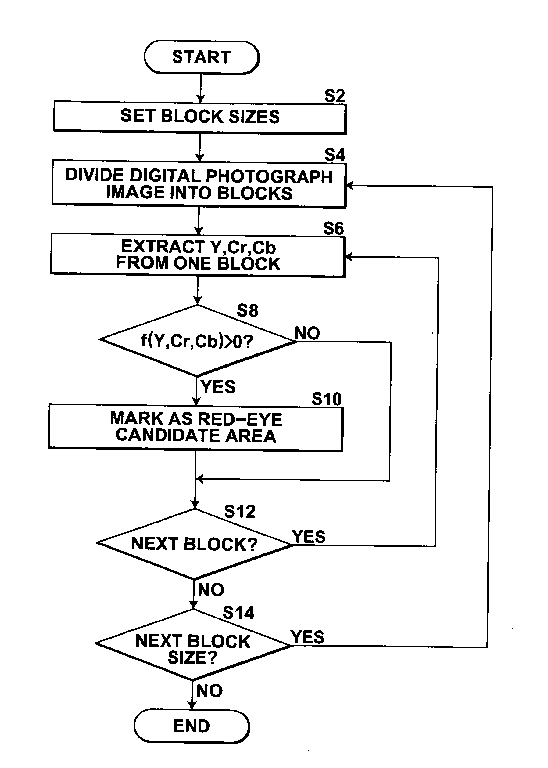
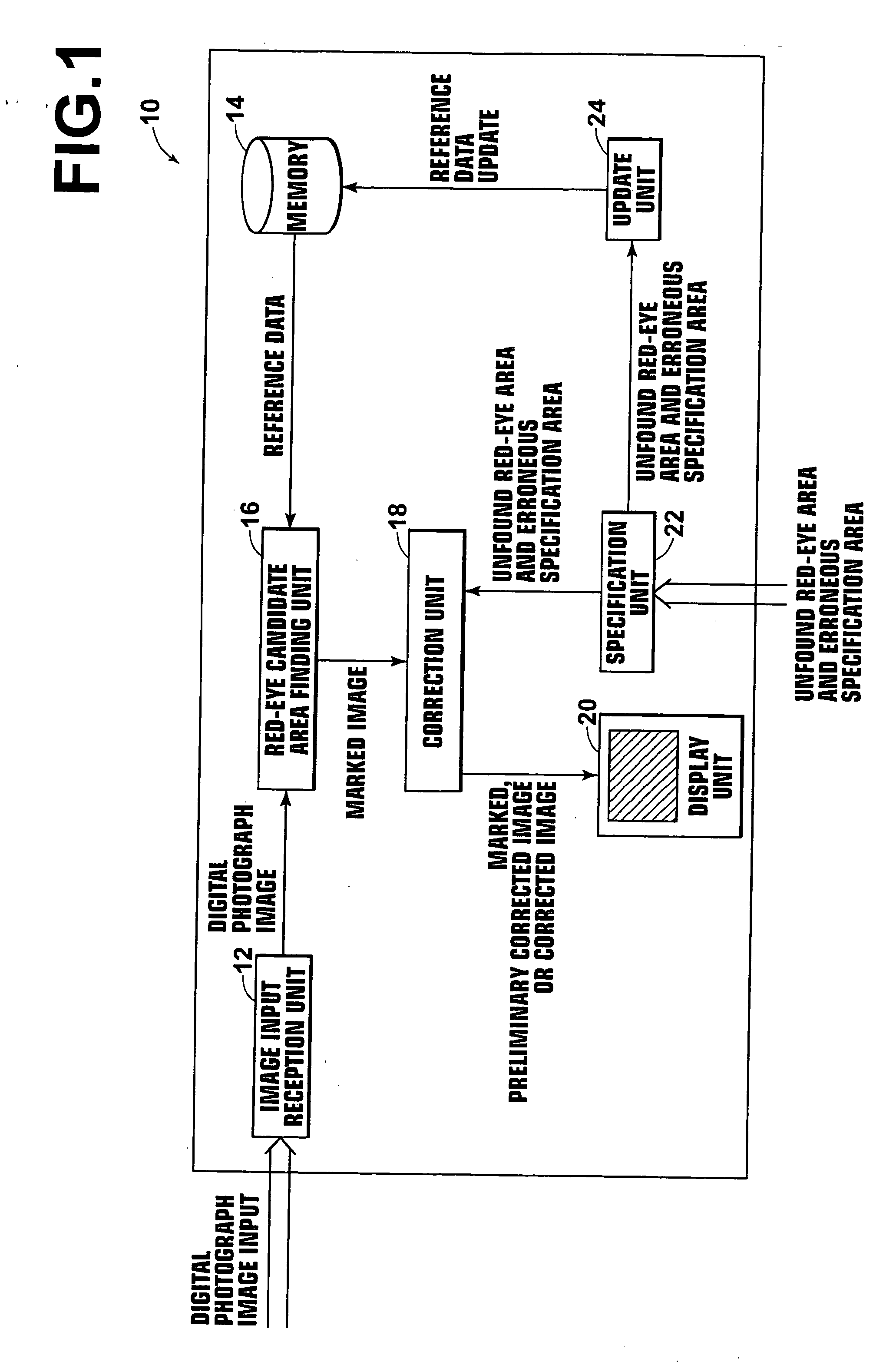
[0047]FIG. 1 is a block diagram showing the configuration of a red-eye detection device 10 of the present invention. The red-eye detection device 10 comprises an image input reception unit 12 for receiving input of a digital photograph image, a memory 14 for storing reference data, a red-eye candidate area finding unit 16 for finding red-eye candidate areas in the digital photograph image based on the reference data, a correction unit 18 for carrying out image correction for suppressing red eye, a display unit 20, a specification unit 22 for receiving specification of an unfound red-eye area and an erroneously specified area from a user, and an update unit 24 for updating the reference data by accessing the memory 14.

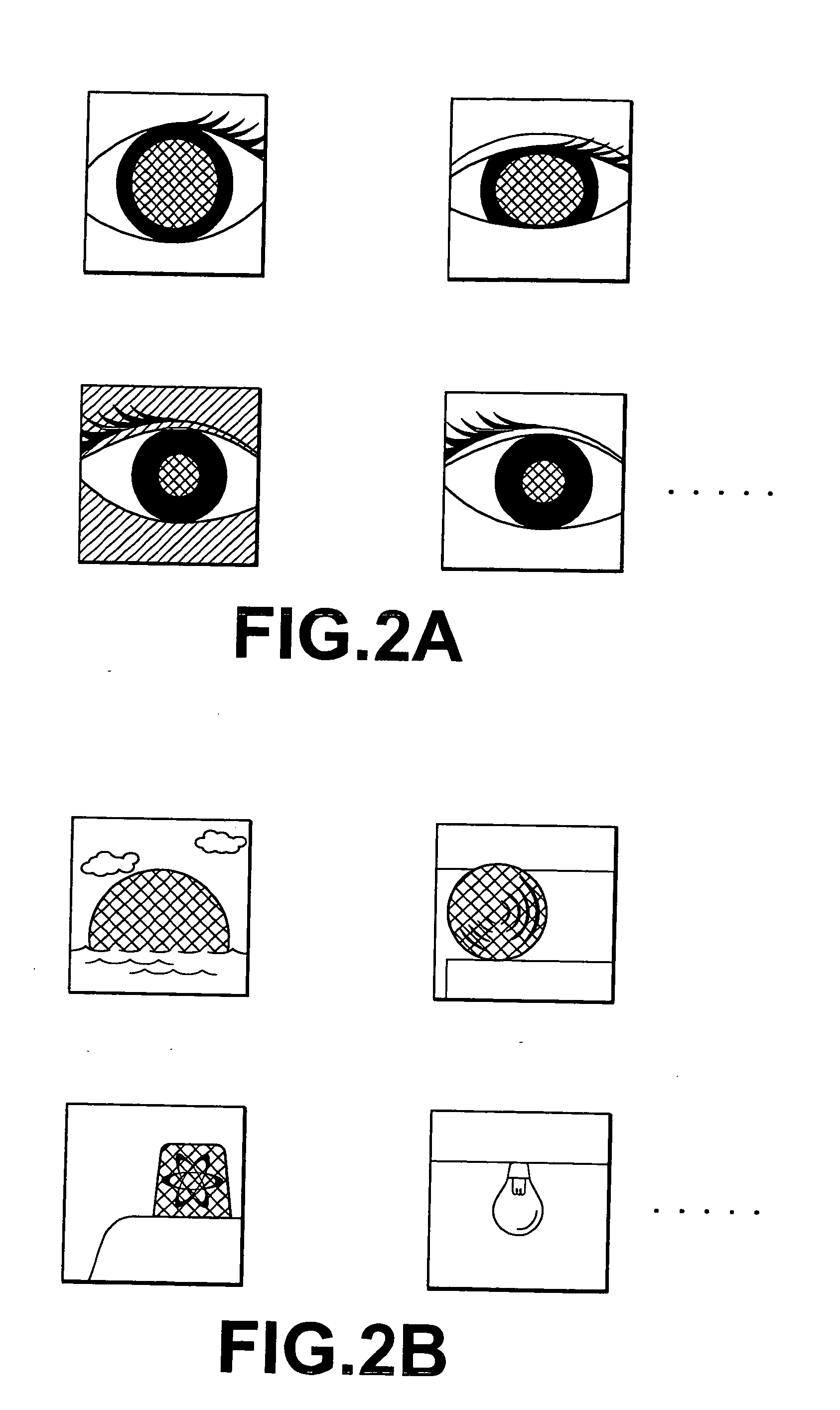
[0048] The reference data stored in the memory 14 define a characteristic of a red-eye area to be detected, and provides a criterion for determining whether or not an area in the digital photograph image input to the red-eye detection device 10 is to be specified as a r...

second embodiment

[0080] Although the red-eye detection device 50 of the present invention has been described above, a program for causing a computer to function as means corresponding to the image input reception unit 52, the red-eye candidate area finding unit 56, the correction unit 58, the display unit 60, the specification unit 62, the update unit 64, the history storage unit 66, the monitoring unit 68, and the resetting unit 70 in order to carry out the processing for red-eye detection and the restoration operation is also an embodiment of the present invention. A computer-readable recording medium storing the program is also an embodiment of the present invention. Various modifications can be made to the program and the recording medium. For example, the processing for causing a computer to function as means corresponding to the correction unit 58 may be omitted to be carried out by another program.

[0081] When a user tries to find red-eye areas, some red-eye areas are left unfound. In order to...


PUM


Abstract

Red-eye area detection accuracy is improved according to a pattern of appearance of red-eye areas generated frequently in an actual photography environment. A red-eye candidate area finding unit finds red-eye candidate areas in a digital photograph image, by using reference data. A display unit displays the image with the red-eye candidate areas having been marked and preliminary corrected. A user can specify an unfound red-eye area and an erroneously specified area by using a specification unit 22. An update unit 24 updates the reference data by learning a characteristic of the unfound red-eye area and the erroneously specified area so that a probability becomes higher regarding detection of an area having a characteristic similar to the unfound red-eye area as a red-eye candidate area while becomes lower regarding detection of an area having a characteristic similar to the erroneously specified area as a red-eye area.

Description

BACKGROUND OF THE INVENTION [0001] 1. Field of the Invention [0002] The present invention relates to a device for detecting red eye, a program therefor, and a recording medium storing the program. More specifically, the present invention relates to a red-eye detection device installable in a digital camera or a laboratory system for digital photographs, a program for detecting red eye, and a computer-readable recording medium storing the program. [0003] 2. Description of the Related Art [0004] The red-eye phenomenon (hereinafter simply referred to as red eye) caused by flash photography of people damages natural appearance of a photograph, which is not desirable. Therefore, various methods of automatically or semi-automatically detecting a red-eye area in a digital photograph image have been proposed for color correction or the like of the red-eye area after photography. [0005] For example, a method of semi-automatic red-eye area detection is described in U.S. Pat. No. 5,990,973. In...

Claims


Application Information

Patent Timeline
IPC IPC(8): G06K9/00G03B15/05G06T1/00G06T7/00H04N1/387
CPCG06K9/0061G06V40/193
Inventor TERAKAWA, KENSUKE
Owner FUJIFILM CORP
Why Eureka
Try Eureka