Retractable optical fiber assembly

a technology of optical fiber and assembly, which is applied in the direction of optical elements, optical apparatus testing, instruments, etc., can solve the problems of affecting the performance of the test fiber box, the size and weight of the inability to use the conventional test fiber box as a jumper

Inactive Publication Date: 2005-10-13
CORNING CABLE SYST LLC
View PDF3 Cites 34 Cited by
  • Summary
  • Abstract
  • Description
  • Claims
  • Application Information

AI Technical Summary

Problems solved by technology

However, the use of a conventional test fiber box as a jumper is considered impractical due to weight, bulk, and cost considerations.
The size and weight of conventional test fiber boxes, however, presents several problems.
The test fiber box is generally too large to fit comfortably inside an OTDR transit case and must be transported separately, resulting in possible loss or misplacement of the test fiber box.
If dropped or inadvertently moved, the weight of the test fiber box can cause damage to the OTDR, to the connector adapter in the optical network, or to the components of the test fiber box itself.
Another problem with existing test fiber boxes is that the jacketed optical fiber and the optical connectors on the ends of the jacketed optical fiber are difficult to manage.
The end lengths of jacketed optical fiber can easily become entangled as they are repeatedly unwrapped and rewrapped, thereby causing stress and damage to the optical waveguide (e.g., glass fiber) and jacket.
In addition, the test fiber box may include a protective lid, which may be inadvertently closed and thereby damage the jacketed optical fiber or connectors.
Furthermore, protective caps (e.g., dust caps) for the optical connectors are easily misplaced, thereby subjecting the connectors to possible damage from dust, dirt or debris.
Although existing test fiber boxes provide for storage of the optical waveguide and connectors, that is not their primary purpose.
However, test fiber boxes typically employ relatively long lengths of unjacketed optical fiber to provide sufficient delay time for test signals to propagate.
The known fiber optic storage reels do not provide adequate means for protecting and storing the long length of optical waveguide necessary for a test fiber box within a manageable size assembly.

Method used


Image

  • Retractable optical fiber assembly
  • Retractable optical fiber assembly
  • Retractable optical fiber assembly

Examples


Embodiment Construction

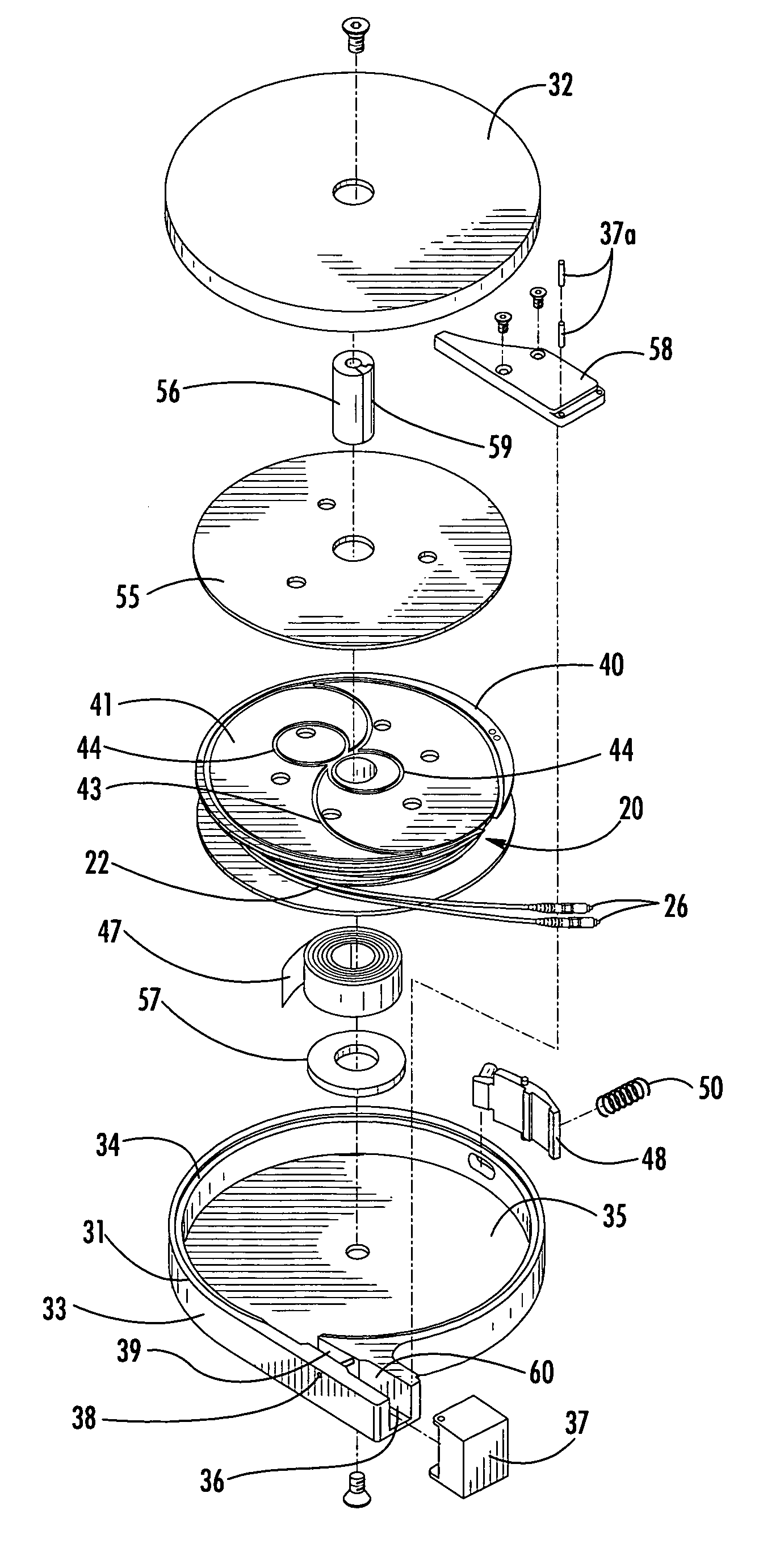
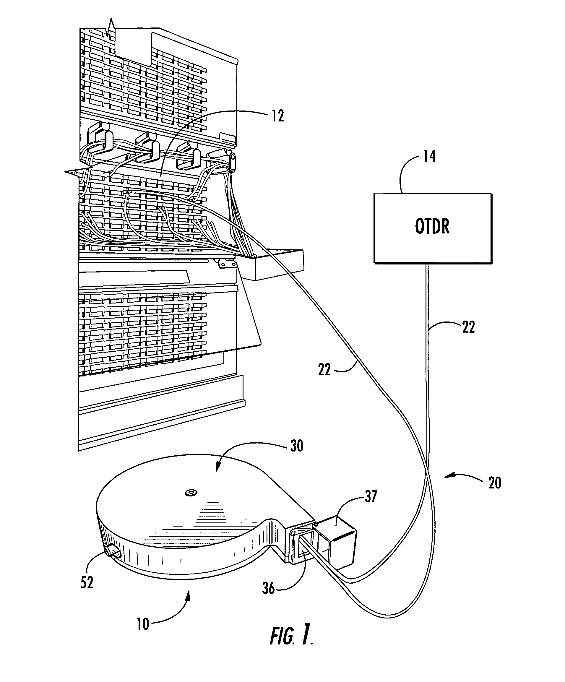
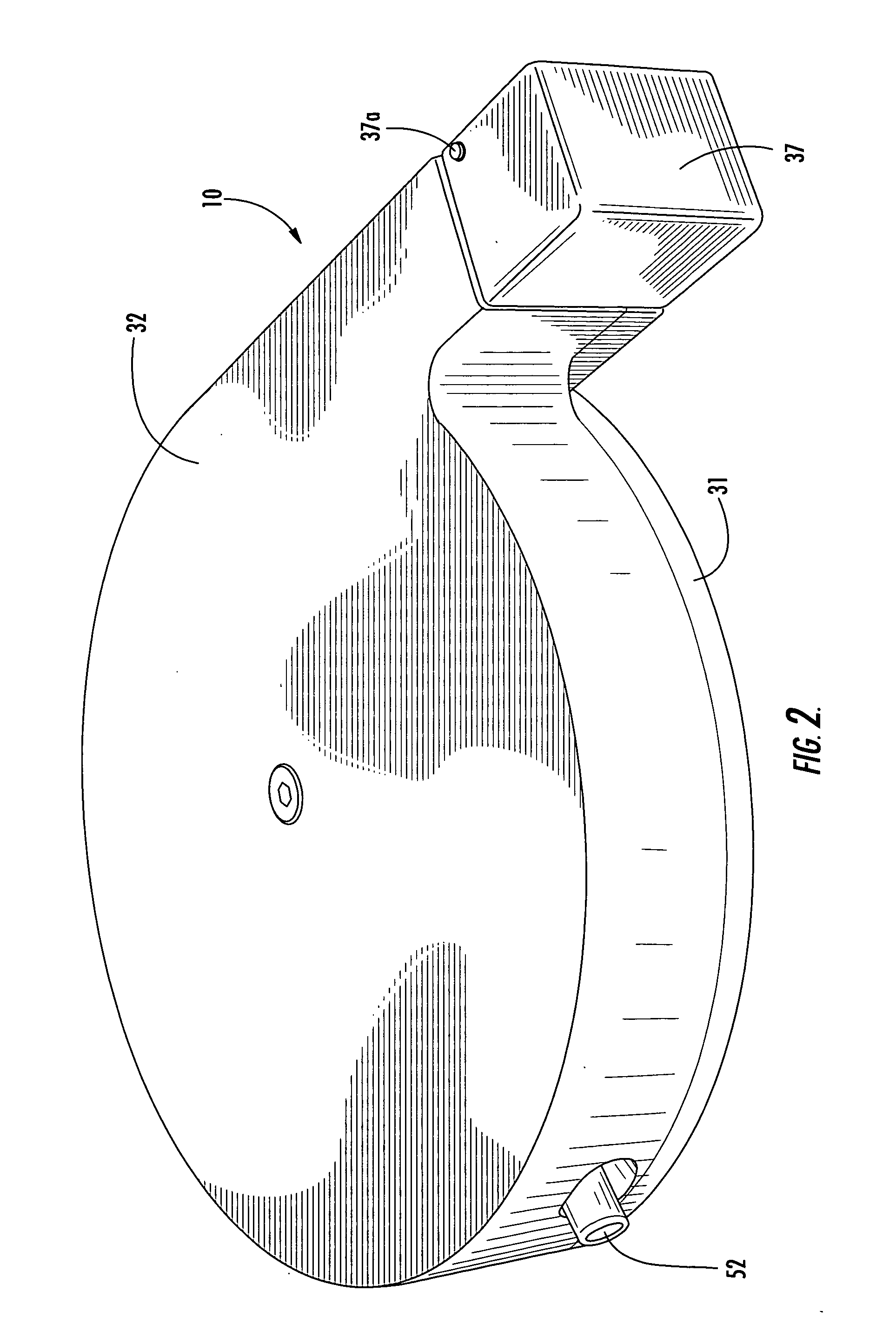
[0015] A retractable optical fiber assembly 10 in accordance with the invention is especially suited for connecting optical test equipment 14 to an optical network 12 so that the optical network can be tested, evaluated, qualified, demonstrated, calibrated, monitored or otherwise analyzed. In the exemplary embodiments shown and described herein, the retractable optical fiber assembly 10 is an improved test fiber box suitable for use in conjunction with optical test equipment 14, such as an optical time domain reflectometer (OTDR), to test the optical network 12. The test fiber box 10 contains a predetermined length of optical waveguide 20 suitable for performing the required testing in conjunction with the OTDR 14. In particular, the test fiber box 10 functions in the same manner as a conventional “test fiber box,”“launch cord,”“launch cable,”“break-out box,”“dead zone box” or “pulse suppressor” to provide from about 50 meters to about 5 kilometers length of optical waveguide to enh...


PUM


Abstract

A retractable optical fiber assembly includes a housing, a spool rotatably disposed within the housing and an optical waveguide reeled onto the spool. The optical waveguide has a central length of unjacketed optical fiber and shorter end lengths of jacketed optical fiber terminating in optical connectors. The optical waveguide is reeled onto the spool such that the end lengths of jacketed optical fiber are extracted off the spool and retracted onto the spool in the same direction. The spool is biased in a first rotational direction relative to the housing by a torsion spring that exerts a retracting force on the jacketed optical fiber. A mechanical stop is also provided to prevent rotation of the spool in a second rotational direction opposite the first rotational direction. In an exemplary embodiment, the assembly is a test fiber box for use with optical test equipment to test an optical network.

Description

FIELD OF THE INVENTION [0001] The invention relates to a retractable optical fiber assembly. More particularly, the invention relates to a retractable optical fiber assembly that can be used in conjunction with optical test equipment to test, qualify, evaluate, demonstrate, emulate, calibrate, or benchmark an optical system, optical network or optical equipment. In an exemplary embodiment, the invention is a test fiber box for use with an optical time domain reflectometer (OTDR) for testing of an optical network. BACKGROUND OF THE INVENTION [0002] A test fiber box, also commonly referred to as a “launch cord,”“launch cable,”“break-out box,”“dead zone box” or “pulse suppressor” is typically utilized in conjunction with optical test equipment to test, qualify and evaluate the transmission characteristics of optical systems, optical networks or optical equipment. Examples of transmission characteristics include loss, length, time delay and reflectance. Test fiber boxes are primarily in...

Claims


Application Information

Patent Timeline
Patent Type & Authority Applications(United States)
IPC IPC(8): G01M11/00G02B6/44
CPCG02B6/4457G01M11/3109
Inventor PONS, SEAN M.
Owner CORNING CABLE SYST LLC
Why Eureka
Try Eureka