
Underwater repeater employing rare earth element doped fiber amplifier, Raman assist and optical pump source sparing

a technology of rare earth elements and repeaters, applied in multiplex communication, electrical equipment, wavelength-division multiplex systems, etc., can solve problems such as significant loss, repeaters changing from amplifying optical signals, and inoperable repeaters

Inactive Publication Date: 2005-10-13
KDDI SUBMARINE CABLE SYST
View PDF18 Cites 25 Cited by
  • Summary
  • Abstract
  • Description
  • Claims
  • Application Information

AI Technical Summary

Problems solved by technology

This makes it such that any failure of the pump source will cause the repeater to be inoperative.
Stated another way, failure of the pump source results in the repeater changing from amplifying the optical signals with significant gain to causing significant loss.
Clearly, such result would be costly to handle, and must be avoided.
Undersea systems are difficult to repair and are required to have nearly 100 percent availability over the entire service life of the system, which is typically about 25 years.
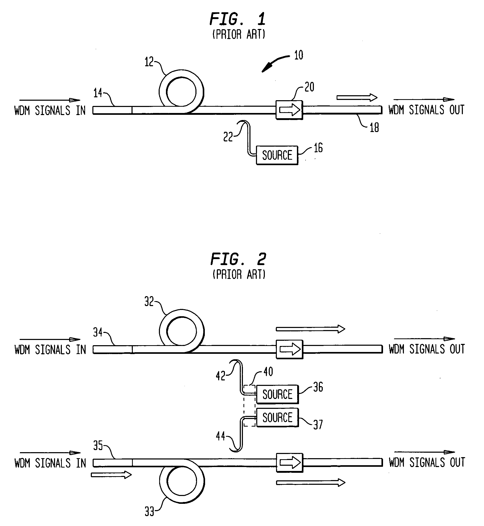
An existing challenge of the prior art is to provide an optical repeater for use in wave-division multiplexed transmission systems which has a consistent flat gain profile over the range of transmitted wavelengths in such multiplexed system.
However, multiple pump sources multiply the cost of the repeater, if multiple pump sources are to be provided for powering each EDFA and each transmission fiber for Raman amplification.
In addition, when multiple pump sources are to be provided each having a predetermined different wavelength, it can be both difficult and costly to obtain the exact wavelength for each pump source.

Method used


Image

  • Underwater repeater employing rare earth element doped fiber amplifier, Raman assist and optical pump source sparing
  • Underwater repeater employing rare earth element doped fiber amplifier, Raman assist and optical pump source sparing
  • Underwater repeater employing rare earth element doped fiber amplifier, Raman assist and optical pump source sparing

Examples


Embodiment Construction

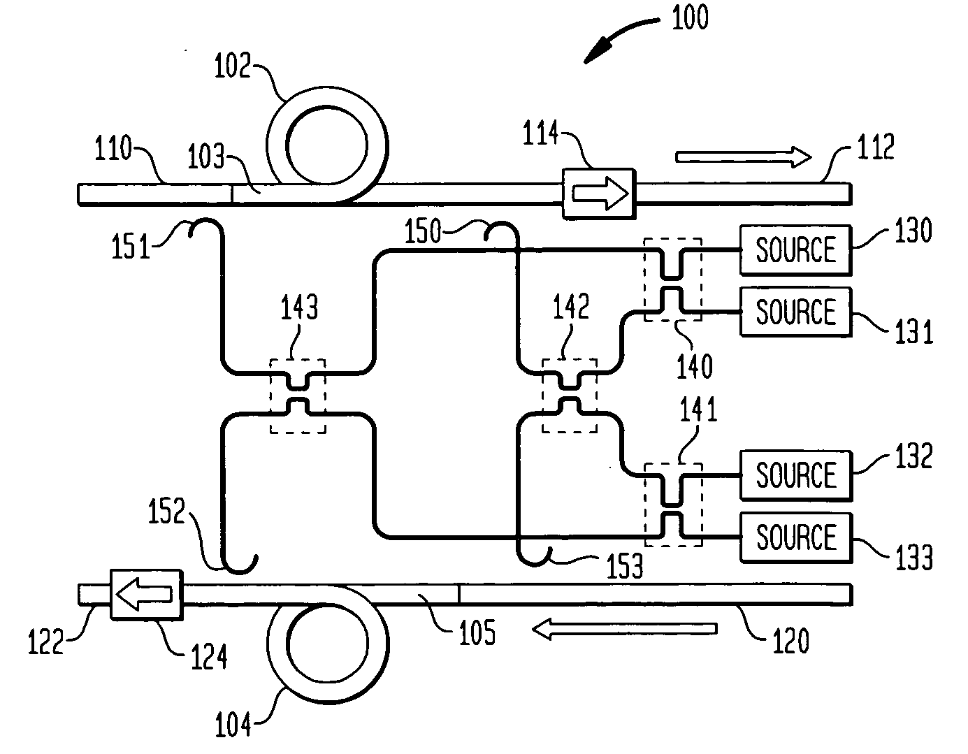
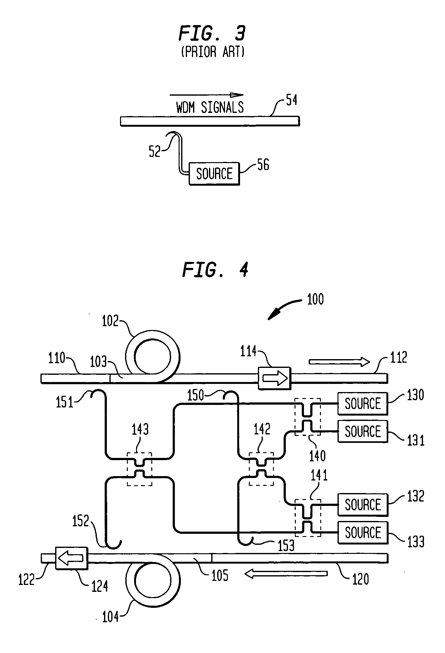
[0026] The embodiments of the invention will now be described with reference to FIGS. 4 through 8.

[0027] An optical repeater 100 according to a first preferred embodiment of the invention is shown in FIG. 4. The repeater 100 includes first and second optical fiber sections 102 and 104, respectively, each of which is doped with a rare earth element, which is preferably erbium. The repeater is shown coupled to optical transmission fibers 110, 112, 120 and 122 for amplifying optical signals carried on the fibers. In the particular embodiment shown in FIG. 4, optical transmission fibers 110 and 112 are arranged to propagate optical signals in a first direction, while optical transmission fibers 120 and 122 are arranged to carry optical signals in a second direction opposite to the first direction.

[0028] The first erbium doped fiber section 102 is inserted into the path of a first input optical transmission fiber 110. The output of the first erbium doped fiber section 102 is coupled to...


PUM


Abstract

An optical repeater is provided which is operable to amplify signals propagated by a pair of optical transmission fibers. The optical repeater includes a first rare earth element doped (REED) fiber coupled to a first transmission fiber of the pair of optical transmission fibers. A second rare earth element doped (REED) fiber is coupled to a second transmission fiber of the pair of optical transmission fibers. A plurality of optical pump sources are provided, there being either four or more pump sources, or at least two pump sources in which each pump source has a different center wavelength. One or more optical energy couplers are coupled to combine portions of the outputs of all the optical pump sources and to distribute the combined portions for insertion into each of the first and second REED fibers for amplification of signals and into each of the first and second transmission fibers for Raman amplification of signals.

Description

BACKGROUND OF THE INVENTION [0001] The present invention relates to optical communication systems. [0002] Long-haul optical communication networks, such as those which carry optical signals across continents or across oceans and other large bodies of water, commonly utilize transmission fibers which are interrupted by optical signal amplifiers referred to as “repeaters” at appropriate intervals, the intervals typically measuring in distances of several tens of miles. [0003] The long-haul transmission of optical signals over optical transmission fibers, including in undersea transmission systems, has greatly benefited over the last fifteen years by the introduction of rare earth element doped (hereinafter, “REED”) fiber amplifiers, among which are erbium doped fiber amplifiers (EDFAs). Such EDFAs and other REED fiber amplifiers are advantageously used in optical repeaters because they do not require conversion of optical signals into electrical signals for amplification and vice vers...

Claims


Application Information

Patent Timeline
Patent Type & Authority Applications(United States)
IPC IPC(8): H04B10/17H04J14/02
CPCH04B10/2916H04J14/0221H04B10/2918H04B10/298
Inventor TRISCHITTA, PATRICK R.GOTO, KOJITAGA, HIDENORI
Owner KDDI SUBMARINE CABLE SYST
Learn More