Combustion burner assembly having low oxides of nitrogen emission

a burner and combustion technology, applied in the direction of burners, combustion types, pulverizing fuel combustion burners, etc., can solve the problems of reducing the efficiency of combustion burners, affecting the environment, and using perforated screens or sheets, so as to achieve low levels of oxides of nitrogen

Inactive Publication Date: 2005-10-13
POWER FLAME
View PDF26 Cites 19 Cited by
  • Summary
  • Abstract
  • Description
  • Claims
  • Application Information

AI Technical Summary

Benefits of technology

[0007] Accordingly, it is another objective of the present invention to provide a combustion burner assembly that provides low levels of oxides of nitrogen emission.
[0008] Accordingly, it is another objective of the present invention to provide a non-flue gas recirculating combustion burner that provides low levels of oxides of nitrogen emission.

Problems solved by technology

One problem with existing combustion burner assemblies is the emission of oxides of nitrogen, which are detrimental to the environment.
Oxides of nitrogen have been found to be one of the primary causes of acid rain, a highly damaging result of the release of sulfur and oxides of nitrogen.
Another problem with existing combustion burners is the use of a perforated screen or sheet at the fuel mixture exit of the combustion burner.
The openings in the sheet, which are generally small, are prone to being plugged by air borne particulates, such as lint.
The sheets are also prone to harmonics generated as the fuel mixture passes through the openings, which sounds like a loud fog horn.

Method used


Image

  • Combustion burner assembly having low oxides of nitrogen emission
  • Combustion burner assembly having low oxides of nitrogen emission
  • Combustion burner assembly having low oxides of nitrogen emission

Examples


Embodiment Construction

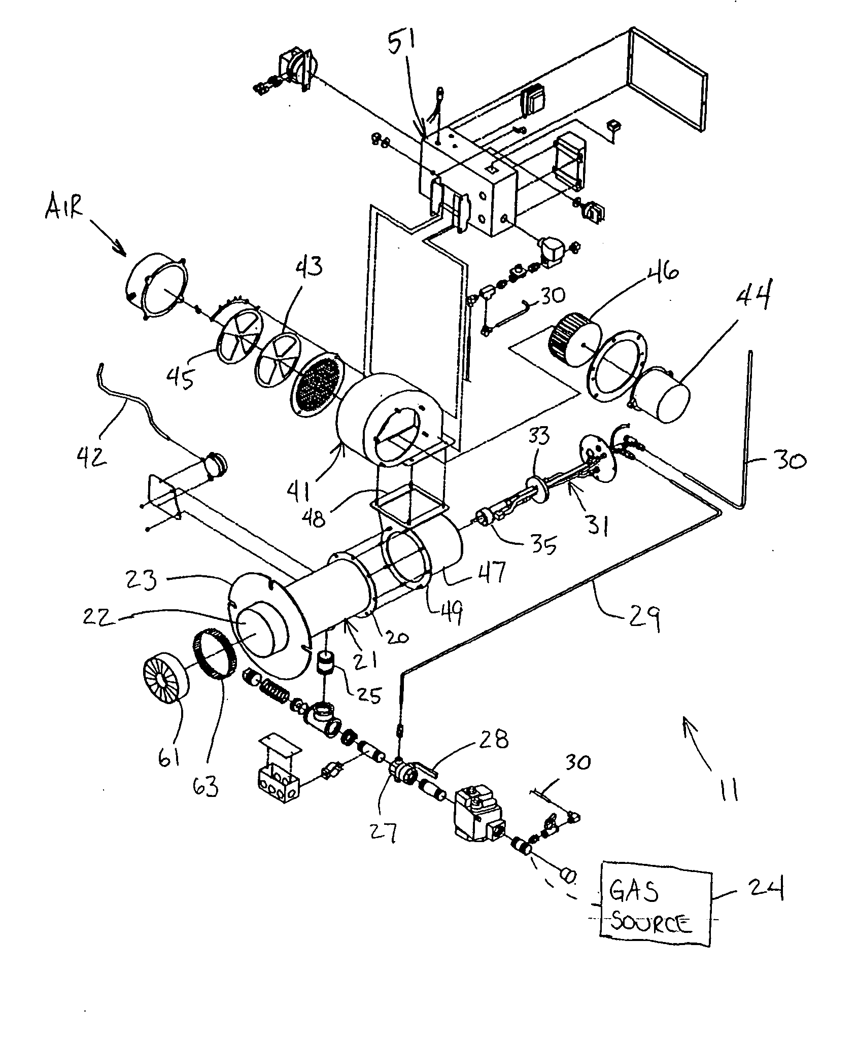
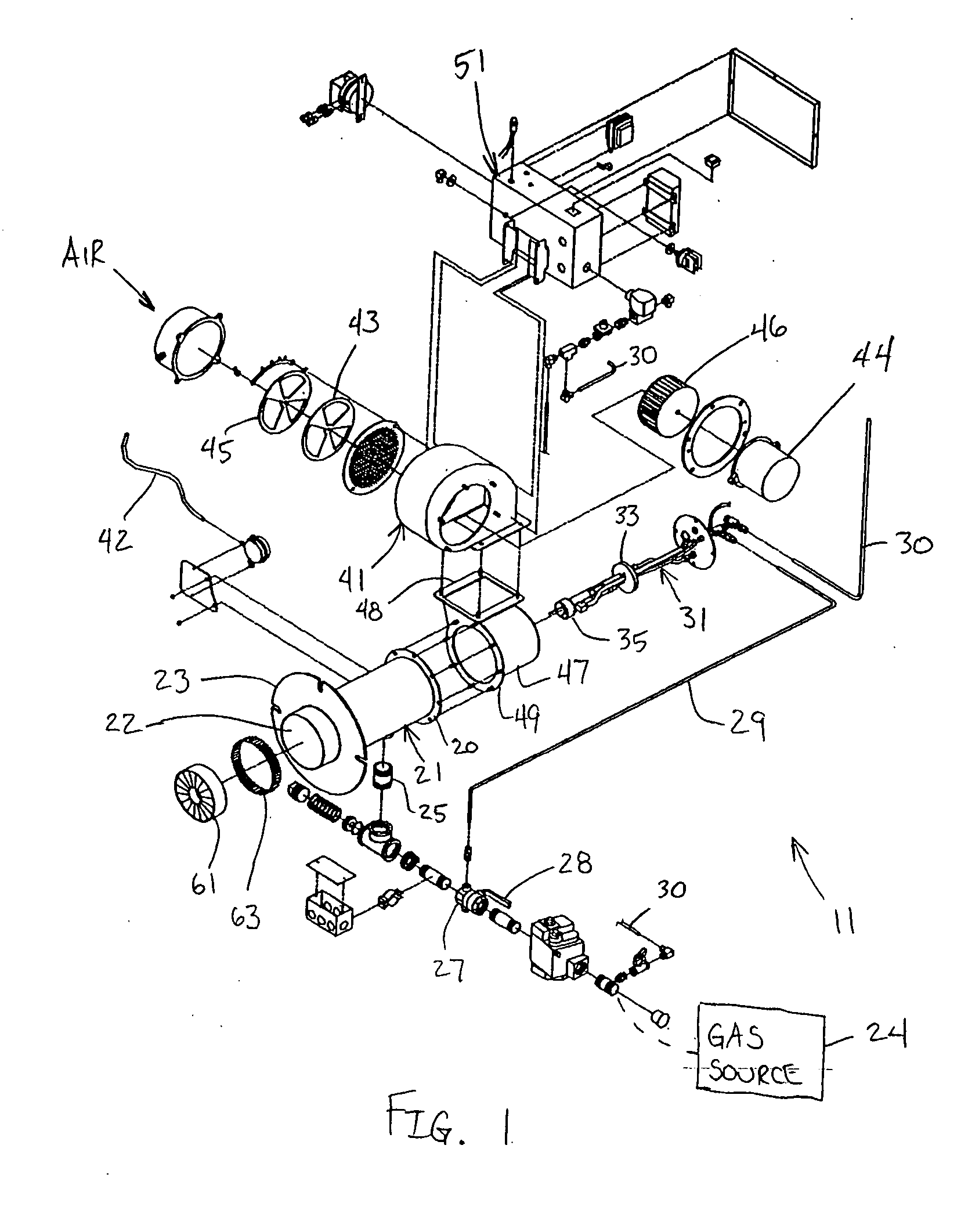
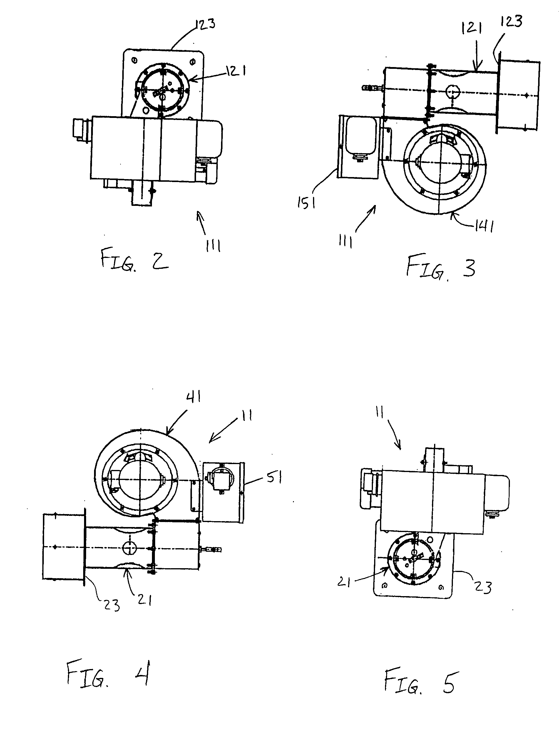
[0028] As shown in FIGS. 1-14, a burner assembly 11 according to the present invention reduces the level of oxides of nitrogen emission. A uniform and lean fuel mixture is provided that reduces the combustion flame temperature, thereby resulting in the reduction of oxides of nitrogen (NOX) emission.

[0029] The burner assembly 11 includes a mixing section 21 in which supplied air and fuel are premixed before being combusted in a heat exchanger 71 (FIG. 14). The burner assembly is rigidly coupled to the heat exchanger 71 by flange 23 at a combustion exit 22 of the mixing section 21, thereby positioning the combustion exit 22 of the mixing section within the heat exchanger. Preferably, the air inlet 20 is at a first end of the mixing section 21 that is opposite the fuel mixture (combustion) exit 22 at a second end of the mixing section. Fuel inlet 25 is preferably positioned between the first and second ends 20 and 22 of the mixing section 21, as shown in FIG. 14. Preferably, the mixin...


PUM


Abstract

A combustion burner assembly having low oxides of nitrogen emission includes a mixing section having an air inlet, a fuel inlet and a fuel mixture outlet. Air is tangentially supplied to the mixing section through the air inlet. A pocket portion in the mixing section receives fuel from a fuel inlet. A plurality of holes in the pocket portion transfer fuel to the mixing section to form a fuel mixture with the air in the mixing section. A diffuser is disposed within the mixing section adjacent the fuel mixture outlet. The diffuser has a plurality of overlapping vanes disposed around an aperture that form a plurality of passages between each of the plurality of overlapping vanes through which the fuel mixture exits the mixing section. A pilot assembly is substantially disposed within the mixing section and passes through the aperture in the diffuser. The pilot assembly is adapted to produce a pilot light downstream of the diffuser that ignites the exiting fuel mixture to produce a high swirling flame, thereby resulting in a combustion burner assembly having low oxides of nitrogen emission.

Description

CROSS-REFERENCE TO RELATED APPLICATION [0001] This application claims the benefit under 35 U.S.C. §119(e) of provisional application Ser. No. 60 / 560,351, filed Apr. 8, 2004, which is hereby incorporated by reference in its entirety.FIELD OF THE INVENTION [0002] The present invention relates to a combustion burner assembly providing low oxides of nitrogen emission. More particularly, the present invention relates to non-flue gas recirculating burner assembly that pre-mixes air and gas to provide a stable flame with low oxides of nitrogen emission. Still more particularly, the present invention relates to a mixing section of a combustion burner assembly that premixes air and gas to provide a uniform fuel mixture prior to combustion. The combustion burner assembly provides a uniform and lean fuel mixture to reduce flame temperatures and retard oxides of nitrogen emission. BACKGROUND OF THE INVENTION [0003] One problem with existing combustion burner assemblies is the emission of oxides...

Claims


Application Information

Patent Timeline
Patent Type & Authority Applications(United States)
IPC IPC(8): F23C7/00F23D1/00F23D14/34F23D14/64
CPCF23C7/002F23D14/34F23D2900/00014F23D2203/101F23D14/64
Inventor GEORGE, KENNETH R.
Owner POWER FLAME
Why Eureka
Try Eureka