Template matching on interactive surface

a technology of interactive surface and template, applied in the field of template, can solve the problems of more difficult to select desired patterns among random scenes, inconvenient real-time interactive systems, and computational intensive differencing methods,

Inactive Publication Date: 2005-10-13
MICROSOFT TECH LICENSING LLC
View PDF99 Cites 127 Cited by
  • Summary
  • Abstract
  • Description
  • Claims
  • Application Information

AI Technical Summary

Problems solved by technology

Pattern recognition systems are generally good at detecting template patterns in controlled environments, but it is more difficult to select desired patterns from among random scenes or when the orientation of the desired pattern in an image is unknown.
However, differencing methods are computationally intensive, since they are typically performed on a pixel-by-pixel basis and require multiple iterations to account for multiple possible orientations.
Thus, differencing methods alone are not conducive to real-time interactive systems, such as simulations that involve dynamic inputs, displays, and interactions with a user.
If encoded tags or simple binary data defining an image or regions of contact are not used, the prior art fails to explain how objects can be recognized using more complex pattern matching to templates.
Until recently, it has been computationally prohibitive to implement object recognition of objects placed on a surface based upon optical shape processing in real time using commonly available hardware.
The accuracy of the results of a template matching process relies on the accuracy of the geometric and illumination normalization process when imaging an object's shape, which has not been fully addressed in the prior art.

Method used


Image

  • Template matching on interactive surface
  • Template matching on interactive surface
  • Template matching on interactive surface

Examples


Embodiment Construction

Exemplary Computing System for Implementing Present Invention

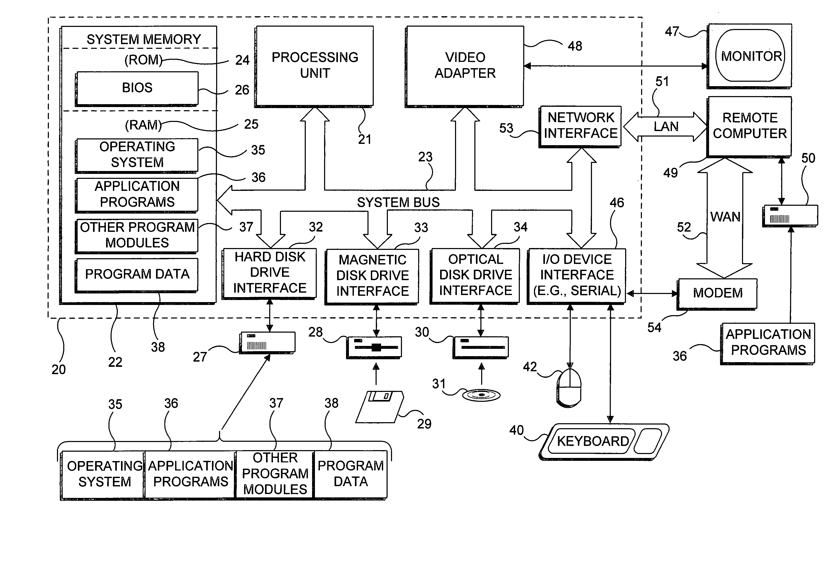
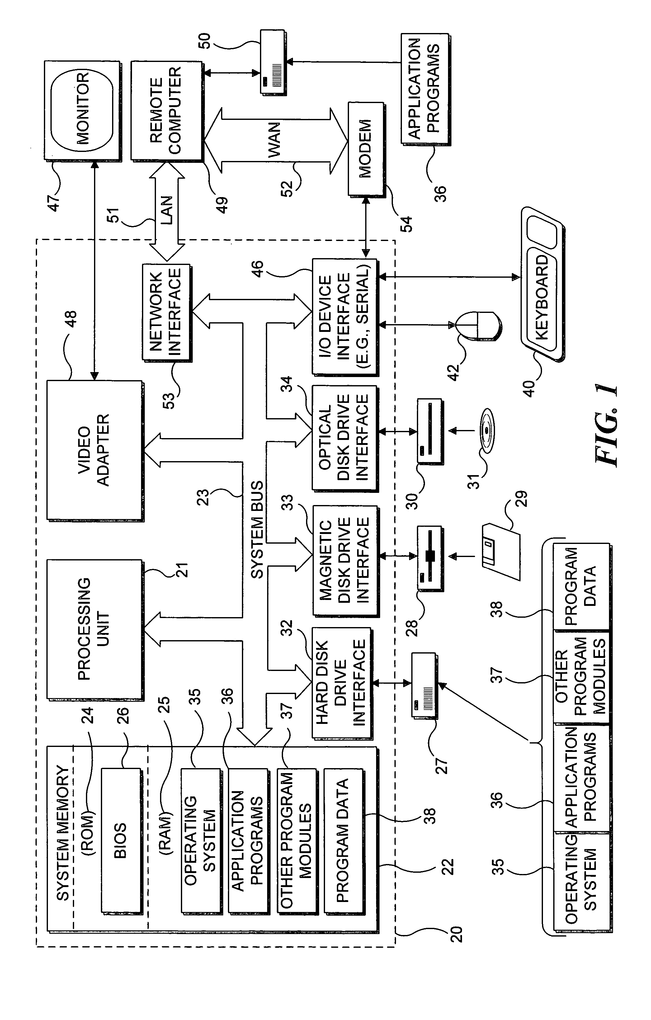
[0031] With reference to FIG. 1, an exemplary system suitable for implementing various portions of the present invention is shown. The system includes a general purpose computing device in the form of a conventional PC 20, provided with a processing unit 21, a system memory 22, and a system bus 23. The system bus couples various system components including the system memory to processing unit 21 and may be any of several types of bus structures, including a memory bus or memory controller, a peripheral bus, and a local bus using any of a variety of bus architectures. The system memory includes read only memory (ROM) 24 and random access memory (RAM) 25. A basic input / output system 26 (BIOS), containing the basic routines that help to transfer information between elements within the PC 20, such as during start up, is stored in ROM 24. PC 20 further includes a hard disk drive 27 for reading from and writing to a hard disk ...


PUM


Abstract

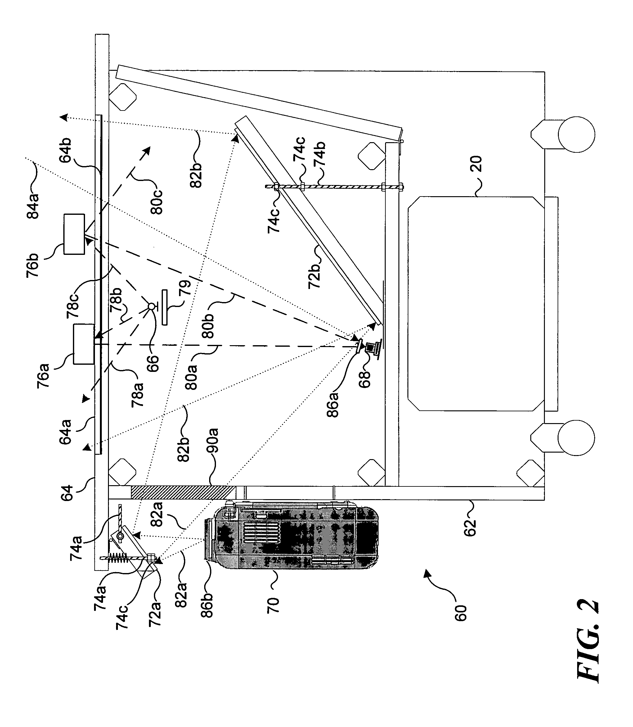
A patterned object that is placed on or adjacent to a display surface of an interactive display is detected by matching an image produced using infrared light reflected from the patterned object with one of a set of templates associated with the patterned object. The templates are created for each of a plurality of incremental rotations of the patterned object on a display surface. To implement the comparison, a sum of template data value corresponding to the intensities of the reflected light is calculated for the image of the patterned object and for each of the templates. These sums are compared to determine a rotated template that matches the patterned object within a predefined threshold, thus determining that the patterned object has been placed on or near the display surface.

Description

FIELD OF THE INVENTION [0001] The present invention generally pertains to the use of templates for determining whether an object is present, and more specifically, pertains to the use of template matching to determine if a patterned object has been present on or near a surface through which the patterned object is detected using reflected infrared light. BACKGROUND OF THE INVENTION [0002] Many barcode systems have been developed techniques for detecting binary code patterns. Some barcode systems use a vision system to acquire a multi-level input image, binarize the image, and then search for one or more binary codes in the binarized image. Also, some pattern recognition systems, such as fingerprint matching systems, use binary data for pattern matching. Although effective for certain applications, it is often desirable to also detect more complex patterns that comprise more than the two values of binary data. Thus, a number of template matching systems have been developed to detect ...

Claims


Application Information

Patent Timeline
Patent Type & Authority Applications(United States)
IPC IPC(8): G09B7/00G06V10/10
CPCG06K9/6203G06K9/20G06V10/10G06V10/7515
Inventor WILSON, ANDREW D.
Owner MICROSOFT TECH LICENSING LLC
Why Eureka
Try Eureka